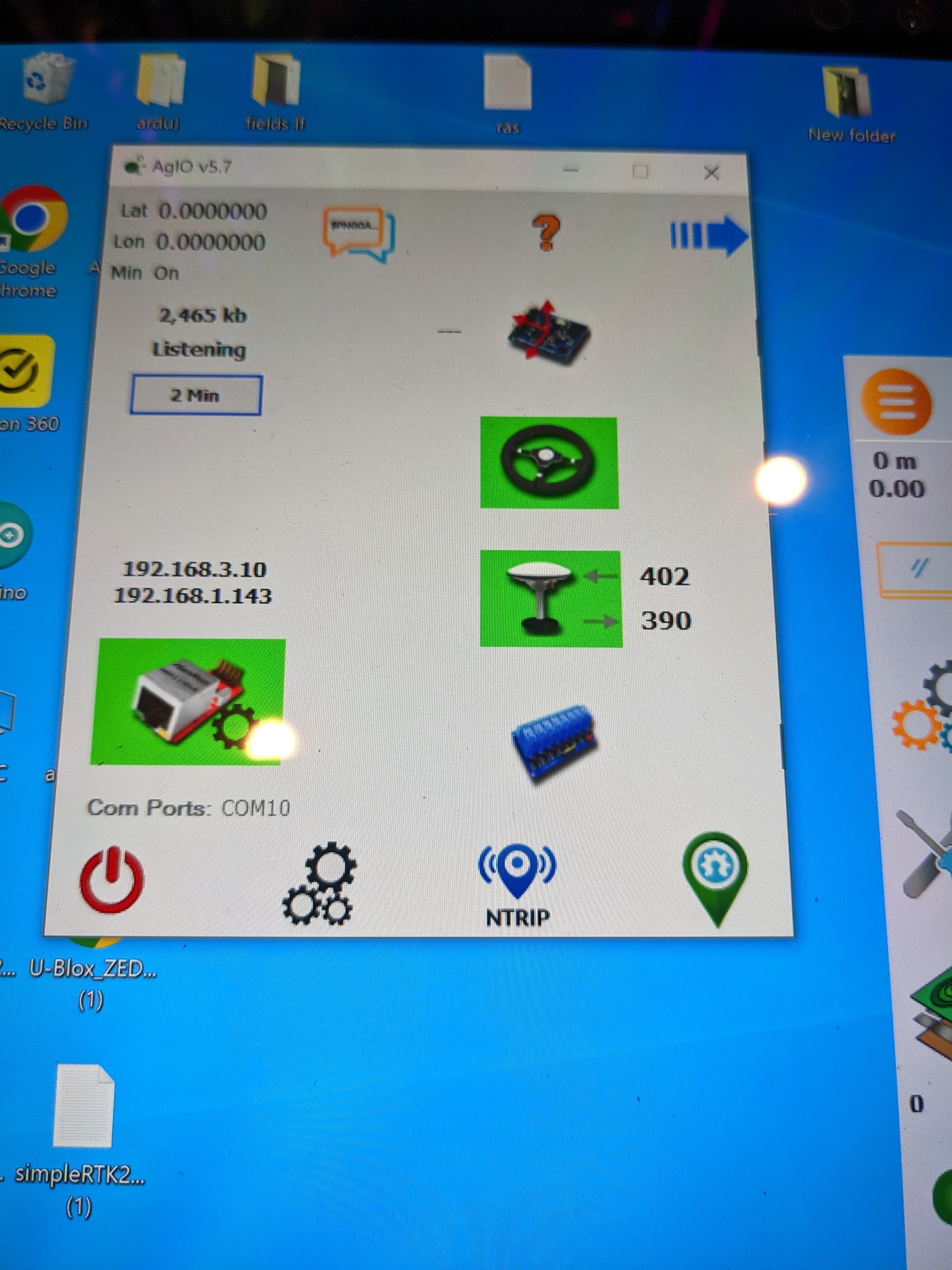
I’m not getting any GPS/RTK LED light at all. (Ethernet is green, Steering is Red). Tablet shows a green UDP icon but all the component icons are neutral (not red or green).
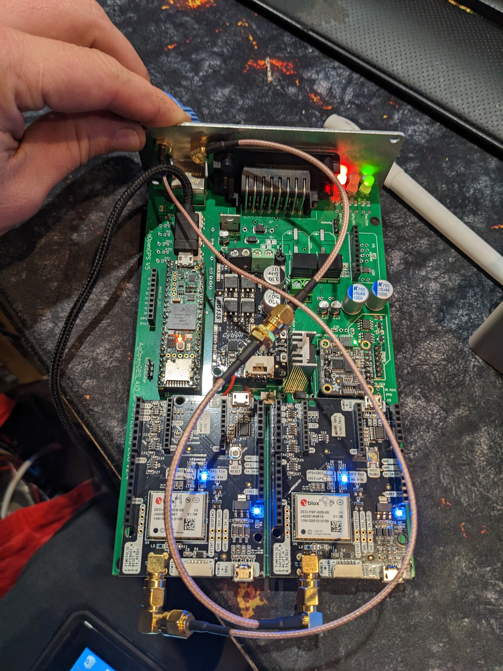
I have my standard pcb on the bench and have attached a WAS and a 12v battery. It’s plugged into the antenna (positioned outside) and to my tablet with an Ethernet (CAT 5e only) cable.
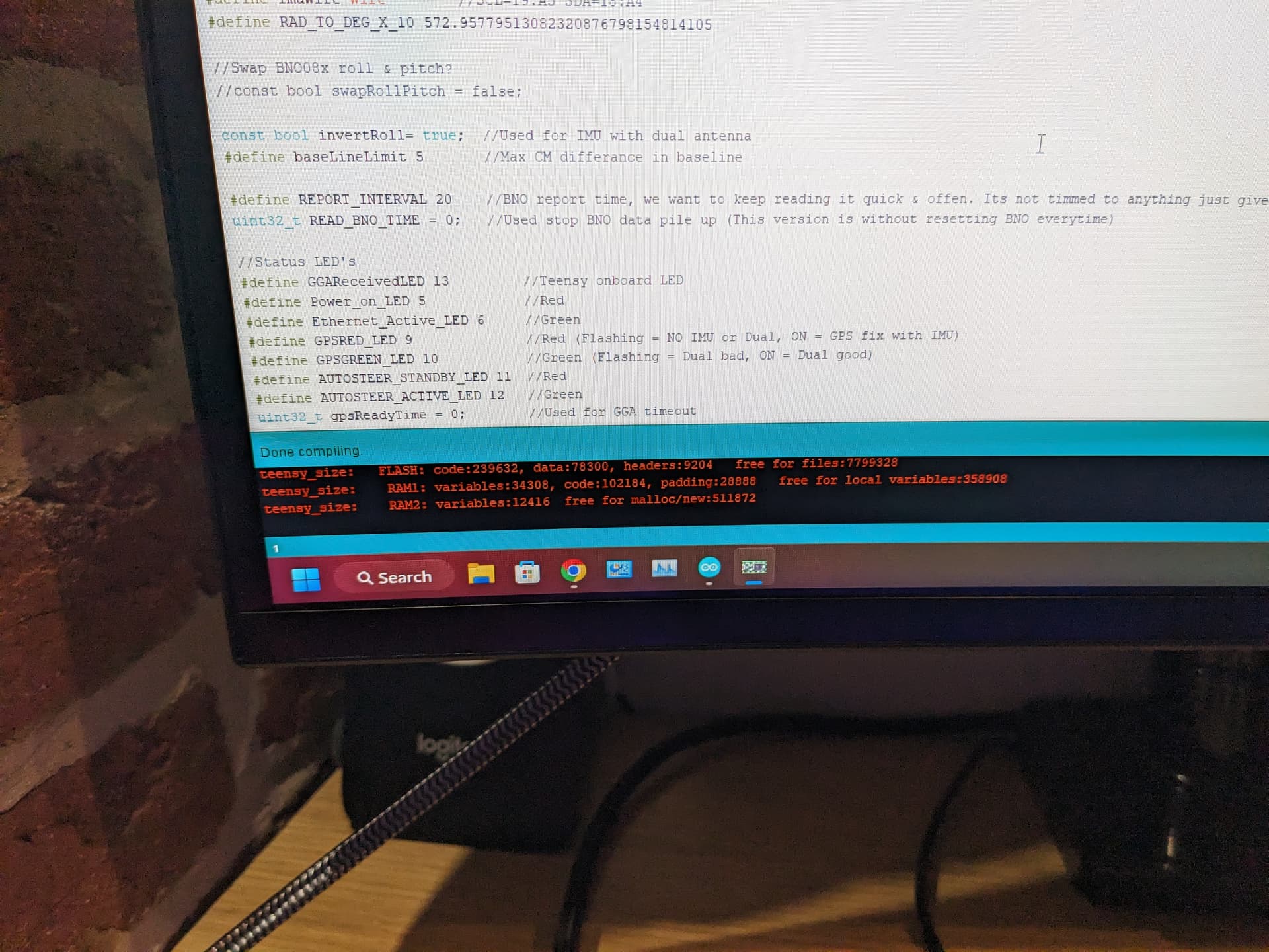
The F9P has the “PWR” light on, “NO RTK” is on, and “GPS Fix” is blinking. Teensy has a rapid orange blink and the BN008X is lit.
When I turn off the PCB and plug the F9P directly into the tablet with usb it shows a green antenna icon.
Any thoughts where to check? I did some poor soldering on the F9P but it still seems to work in isolation.
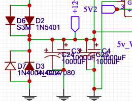
Where are you guys locating the 12v/24v converter? I have a standard size, single F9P board with the 3d printed case and wondering where to wire it in. Have people drilled an additional hole to get wires to the 24v input terminal, or have found a converter that fits inside the case with the pcb and getting 12v from the board? Thanks!
I also have a problem, the gps/rtk led does not light up. The old version worked (5.6.2) but when I updated to 5.7.1, teensy 5.5 and f9p 1.32 doesn’t work, f9p won’t connect. Are the versions compatible? Do I need to change the baud rates?
No don’t put converter in the case, not a good idea having electrical interference so close to PCB.
The converter needs keeping cool as well, put it somewhere else in the cab and just run cables to the box.
I use Hammond cases and bring the 24V in through the back panel.
Nothing wrong with you settings. You can move the text where you want it. We put both smd and tht components and the names overlap in places. We were more concerned with being able to get component options than with neatness.