If you solder to any of the points that I noted, you do not need to buy anything.
So if I connect this point and pwm2 with a cable, it will be ok?
I don’t know if I can do it, these are quite microscopic elements
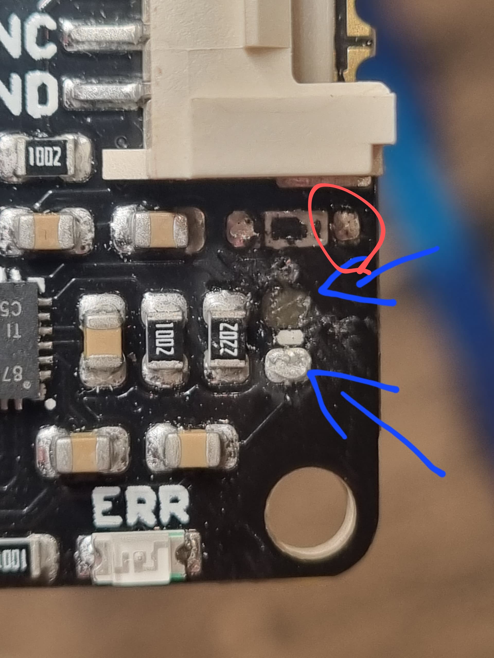
Yes, you can and there, overlooked.
Hi, I wanted to connect 1 directly to pwm2, I know that you can also connect to NC and then connect the cables from the cube to the PCB connector, but I wanted to do like most users. At 1, my soldering pad broke off (I wrote about it above) Since 1 can be connected to NC and directly to PWM2, will it be the same with 2, I know there is a YouTube guide on how to make a freewheel mod, but only 2 can be connected to NC there, I would like to find out if link 1 with pwm2 directly can I connect 2 in the same way
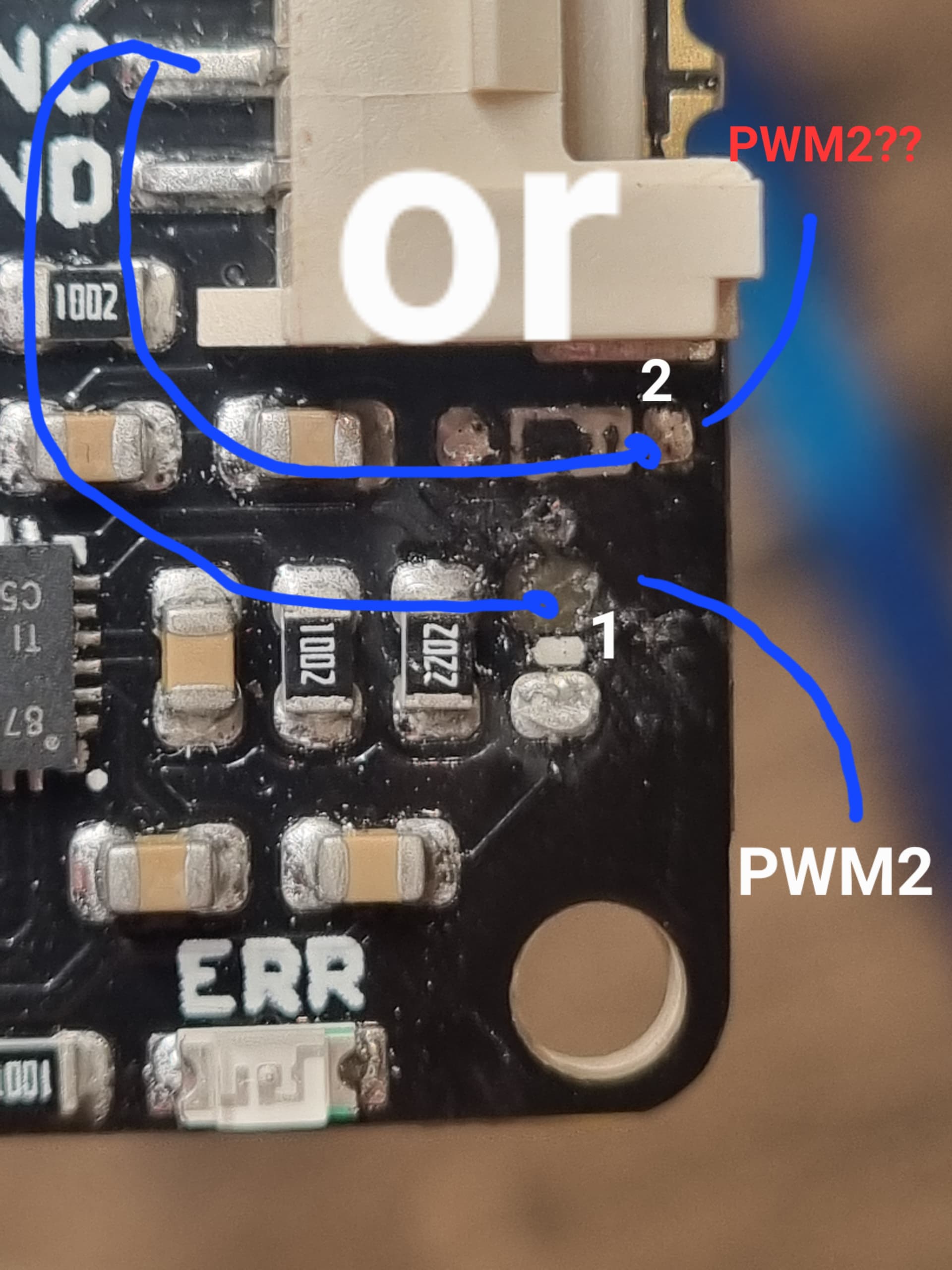
1 & 2 are connected on the Cytron pcb, so they’re the same thing.
Your Cytron has the free wheel mod on it. Your PCB probably needs the pwm2 free wheel mod fix to send the correct signal to the Cytron
I can’t seem to find a description or details of what I still need to do to mine, can someone point me in the right direction? Is there anything else missing or wrong on this board?
1 Like
After doing this does something need to come off the PWM2 hole on the board to either the cytron or somewhere else on the board?
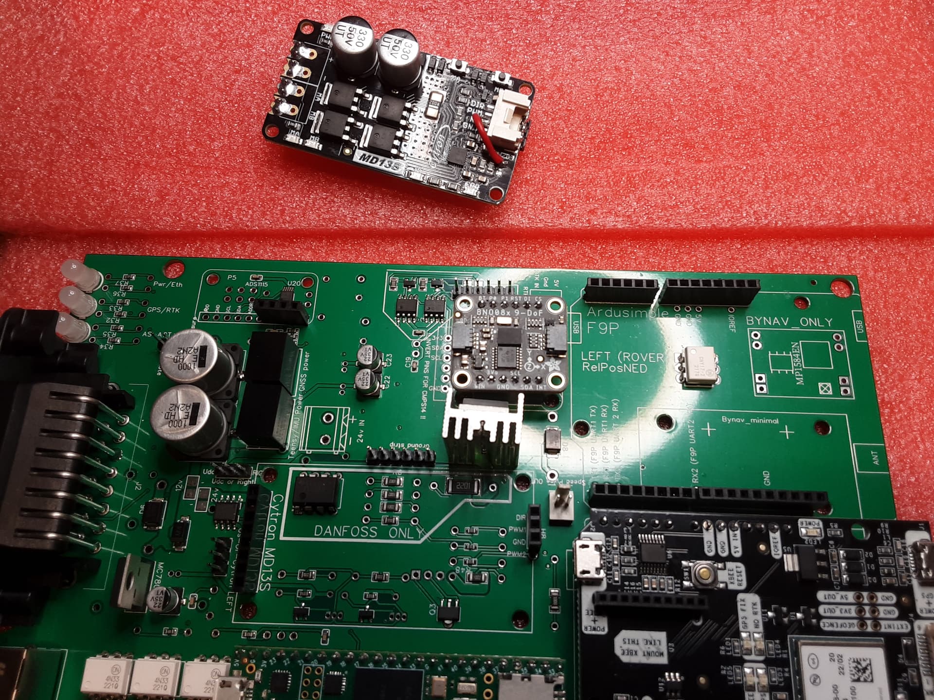
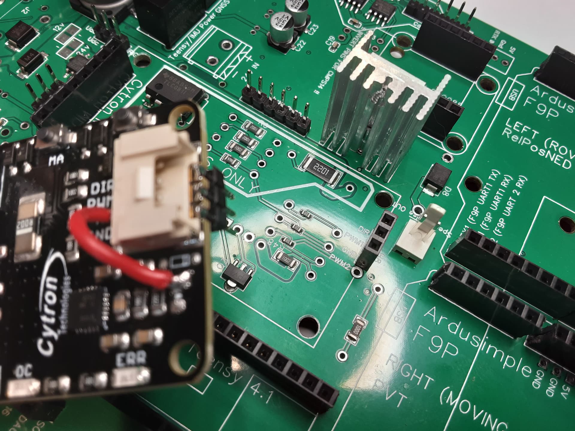
Mine has the three pin header and I edge soldered those to the cytron. Where does that red wire run to?
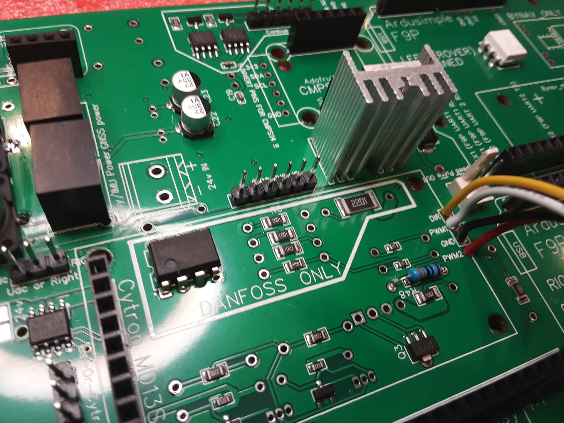
As an alternative to cutting the trace, could I simply remove R48, similar to how I removed the components from the cytron? Or is the point of this to double the possible current accross?
That is seeming more right looking at the schematic. So now, my questions that remain are still the destination of that red wire, and how does one safely cut a trace? I’m no electronics heart surgeon…
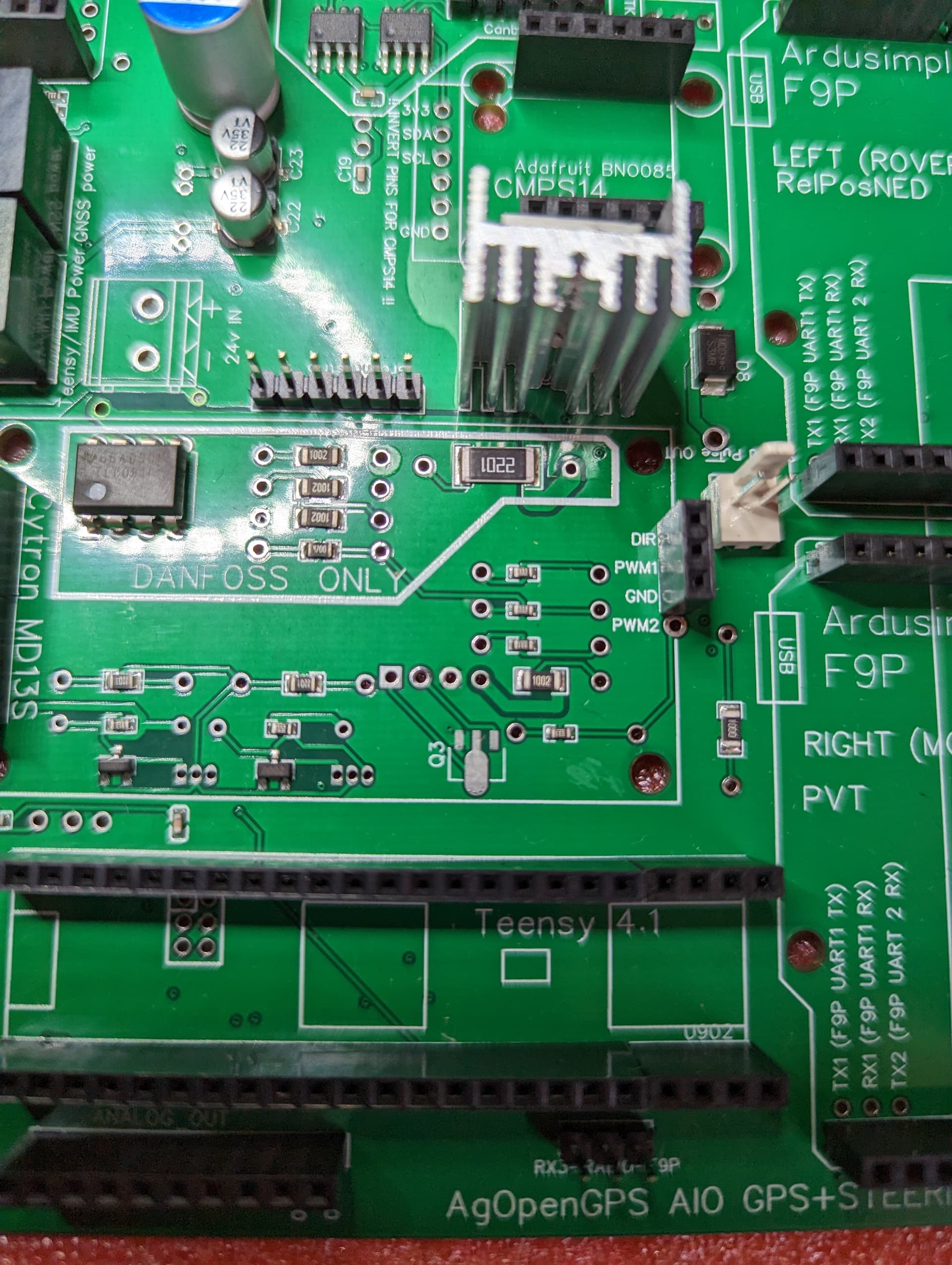
After cutting the trace and adding a resistor, the new resistor goes from the Teensy PWM IO to the Cytron PWM2 pad and the old R48 is still needed to go from the Teensy PWM IO to the transistor that control the LOCK output FET.
I use a dremel with thin cutting wheel. You can also use an exacto knife, just take care to NOT slip and cut other traces or yourself!
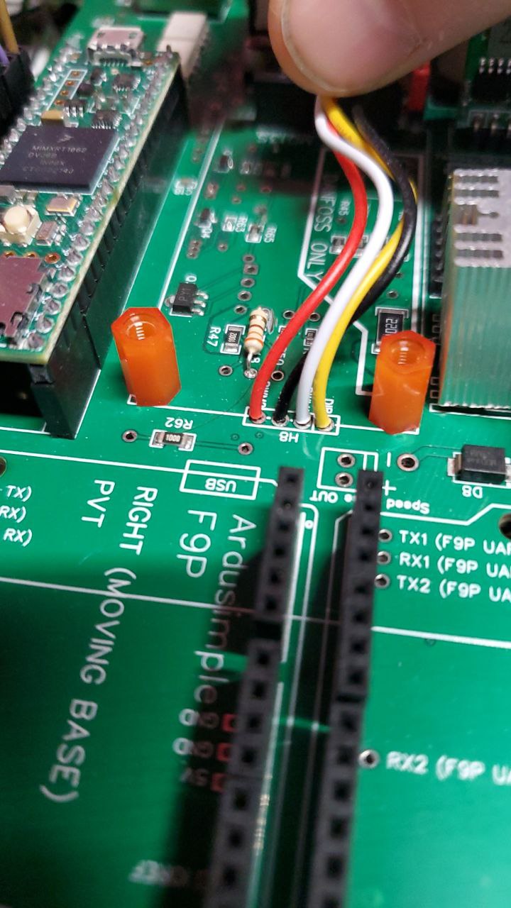
Those 4 wires are the Cytron’s included wire/connector/jumper. I cut it in half, the solder them into the the 4 pads (dir, pwm1, gnd, pwm2) paying careful attention to the order/color of the wires and plug that into the Cytron instead of using the 3 pin header.
You can also use an external relay controlled by LOCK output instead of the free wheeling mod but seeing as you’re this far already, I would unsolder the 3 pin headers and use the wire/connector instead.
on the Standerd board on which F9p does the xbee radio go if i am using LR for RTK?
The main/right/position f9p
I would like to understand this better. With the freewheel mod shouldn’t the NC on Cytron be connected to the PWM2 on the main board? And what happens under of that white connector coming to the 3pin HDR? Looking at the codes on boards I assume DIR-DIR, PWM-PWM1, skip NC and then GND-GND? And the white connector doesn’t skip NC hence the different order if using the connector wires? And the order of the pwm2 and gnd soldering holes on AIO B have changed from for example Kaupoi 4.1 Board to accommodate the use of that 3P HDR? Why the recommendation not to use that 3P HDR then?
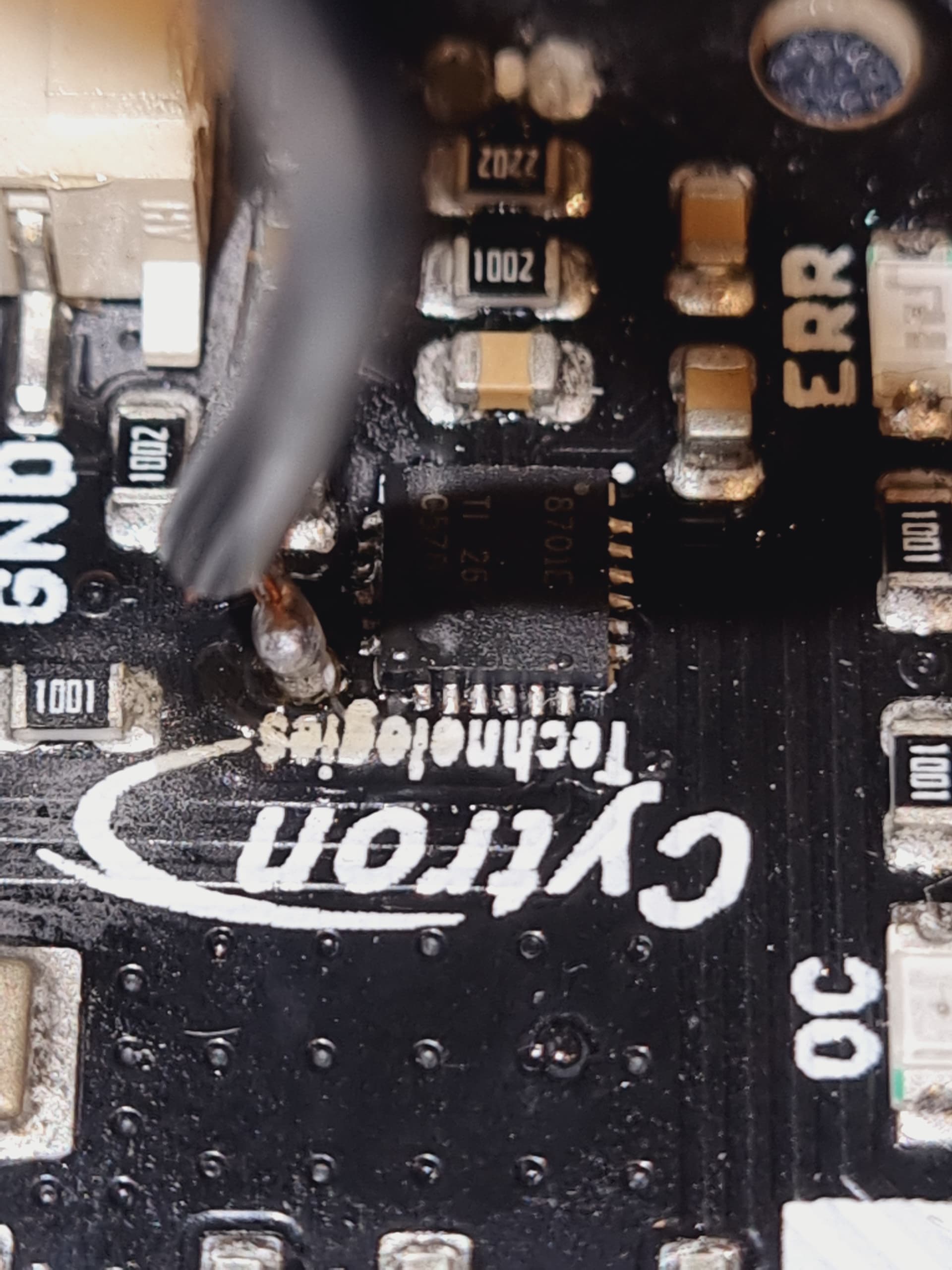
Hi, yes I know I did a stupid thing and destroyed my citron, I’m waiting for a new one but I would like to see if this one works, I’m afraid that it may damage something, although I don’t see anything soldered together, tell me the safest way to check if the citron works so as not to damage the engine and pcb
1 Like