I’m wondering about this too, in the 59th message it says one gps and one imu available.

5 Likes
Out of curiousity, are you cutting the rest of the field like that and if so, how are you swapping the offset each turnaround?
1 Like
Is the ino ready to go? Which pins for the motor driver?
Nope only a few rows for boundary
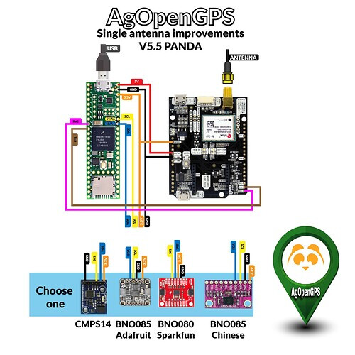
Yes ino it’s ready, only needs a new ino and Teensy, AOG supports PANDA, you don’t need modify any wiring of normal setup
Interesting - I can just upload a panda ino to my nono pcbV2?
PANDA requires a different more powerful micro controller. V2 is just effectively an input/output card.
Panda syncs the imu and gps heading, as well as makes the gps available on Ethernet.
Currently the easiest way to think of Panda is GPS heading upgrade.
Panda is sent to the tablet program, the tablet program uses the position and fused heading for more stable output, the tablet program sends commands to V2 to finally steer the tractor or sensor and switch input is sent to the tablet. (electric motor steer, existing hydraulic steer)
If you are running off CAN, this may be different.
Panda takes the last minor wobble out of the heading.
2 Likes
I couldn’t figure out something, I am using the PCBV2 Brian card udp + bno udp running at the moment, and no problem, but I want to switch to Panda, I wonder:
1-) After installing the panda card, connect and give to switche with udp. Can I run directly at 5.6.2?
2-) Which one should I install GPS and Panda2 on the Basic Panda in the Support folder?
3-) Finally, I do not understand, imu teensy is connected to the card in Panda, but for imu, there are Bno code for Arduino nano.
1 Like
I think the PANDA magic only works if the imu is directly connected to the teensy.
PANDA is the NMEA sentence created to send to 5.6.2 over UDP
I also have to figure out what to do switching between Panda and non Panda.
@Vili does receiving the “panda” sentence automatically ignore a imu left connected to the V2 board?
Yes you need IMU connected to the teensy. I never tried to leave the IMU on the PCB, why you need switching?
The reason is easy upgrade for soldered in users, and the fun of switching back and forth to compare Panda to Pre Panda.
Basically if Panda exists Ignore any other IMU input.
Also saves having to mod the fleet all in one go.
Thanks.
So which board are we using for the Panda teensy card?
Is it possible to use an orange pi instead a teensy ?
The teensy 4.1
1 Like
I am using an ardusimple base / rover with xbee radios for rtk. Will the arduino teensy 4.1 be powerful enough to supply the power for the ardusimple with radio board? Don’t want to ruin anything.
The 5V off the teensy or the f9p is regulated from usb port, so it goes right from usb to pin. 3.3V is the limited one.
Currently just powered up my first PANDA from F9P, 30 min, no smoke yet.
Thank you @Vili for the detailed notes in the .ino for f9p config. Setting up with a Sparkfun board using f9p 1.32 firmware. Its working!
1 Like
No. The ino code is designed for the Teensy 4.x’s hardware.
I’m sure it could be ported to run as a Linux binary on the Orange Pi, but that would be overly-complicated and over-kill in my opinion.
1 Like
Ah ok!
I just saw someone with a board that had the teensy, imu and gps board all on the same pcb and wondered if that was standard practice.
That would probably be the easiest route with the AOG standard ardusimple board.
Custom pieces custom problems, I now have to 3d print a box for the parts vs having a nice PCB. Could not wait any longer to try the PANDA.