Well done! We need this kind of information for our project! May I ask how you managed to find out which PGN and which bytes on the vehicle bus are used for the speed. Did you start with a known ISOBUS message and then looking for a vehicle bus message with same values …?
Hi Guys,
i need a little help.
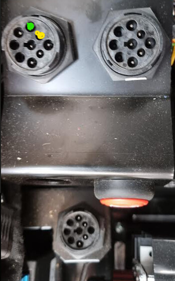
I would connect a Case Puma with MechanicTony Teensy board like this
If i connect the Pins H and J behind the seat with CAN3 an the board i have a connection. I see the steering angle. The simulator is on. but i could not manually move the tires. To isobus i have also no connection.
Has anywone a Idea?
Thanks
Remember that the tractor must be moving for the wheels to turn.
If the tractor has never worked with navigation, you must enter the H menu and configure the valve.
HH Menu is done.
good then i trie to drive
Hi all,
Im trying to get my fendt 722 on agopen, did the things like steering with a small angle steering sensor all with succes. The guys helped me the most are Commonrail and Alan by posting their findings, shout out to them (Y)
Now i’ve set up a prototype with the teensy 4.1, BNO, f9p, LM2596 and 3 can bus receivers. Alan did the most of the research i just read a lot and just trie. And because of a picture of his setup i could make my own prototype and im good to go i think. But…
Im a little bit scared of destroying anything. On all the reading and studying scheme’s pictures pcb’s etc i see diodes and resistors, on the picture of Alan’s setup on the rooftop Fendt i don’t see any. Can i try it without? Or do i requesting the gods ![]()
1 Like
Diodes aren’t required for driving via the CAN bus. They usually are used in conjunction with driving a steering motor or controlling the coils on the hydraulic valve block directly. If you’re doing all your control via CAN, the CAN transceiver chips do all the signaling in the silicon and are self-contained. A 120 ohm resister between CAN HI and CAN LO might be required depending on where in the CAN bus you’re connecting. But worst case without the resister it just won’t work and you’ll get CAN errors on the tractor. But it can’t harm the tractor. Working with CAN is fairly safe. CAN was designed to be a very robust system and can deal with dead shorts even in a safe manner.
Thanks (Y)
this weekend i’ll try to connect
Really sorry, I now remember your message. Lots going on and I forgot to reply. No Diodes or resistors needed. This is the stripboard circuit I use now. Jusi some small capacitors on the transceiver power pins. No pictures of the other side. It’s quite ‘busy’ but you get the idea of what I used. The BNO085 is mounted separately, as it was on my prototype setup. GPS serial and Ethernet comms are also on it now but I can’t find that picture either. It has worked well until the steering rotation sensor on the tractor developed a fault. I now need to remove the cab to replace the sensor! ![]()
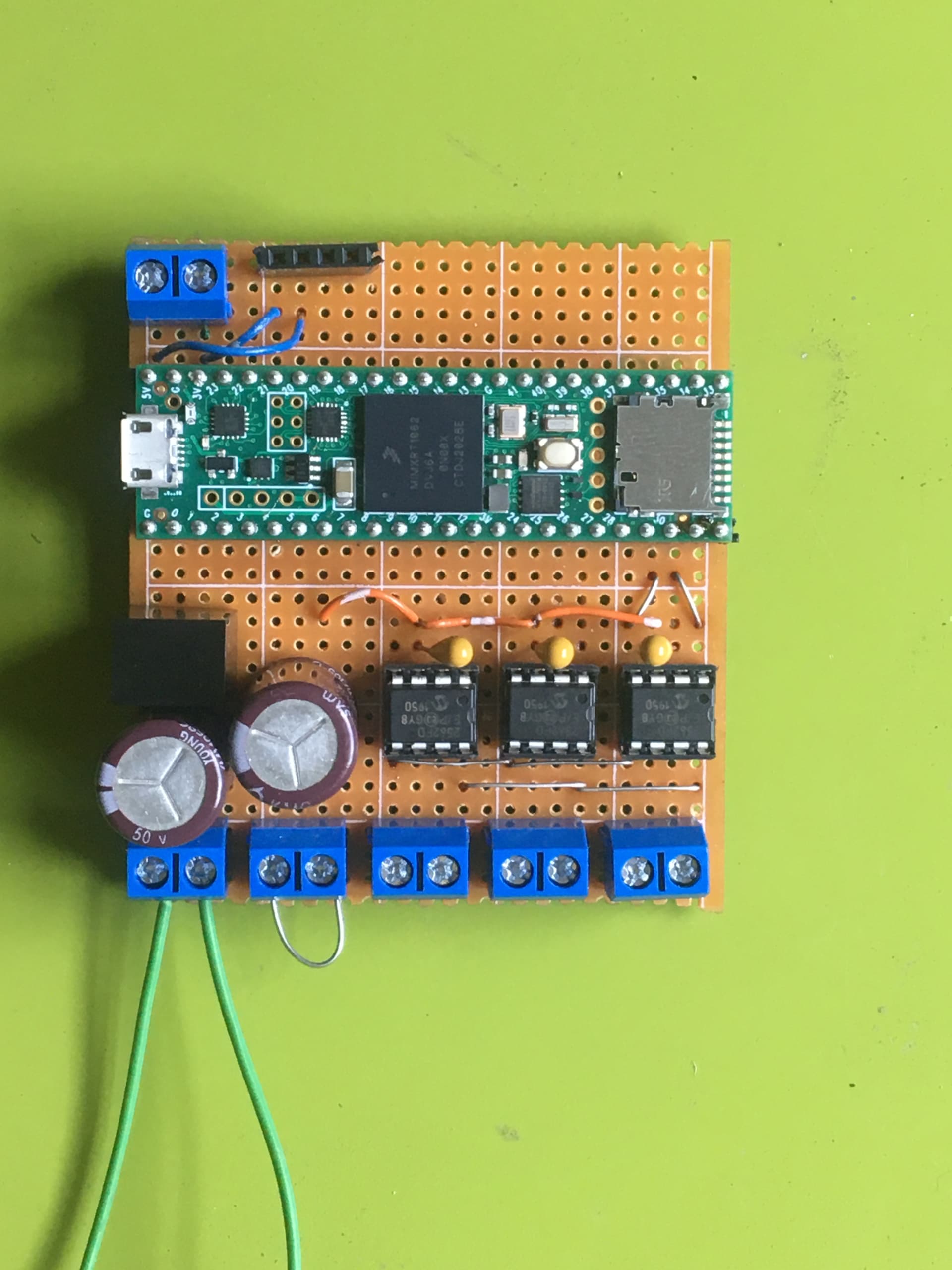
[Edit…]
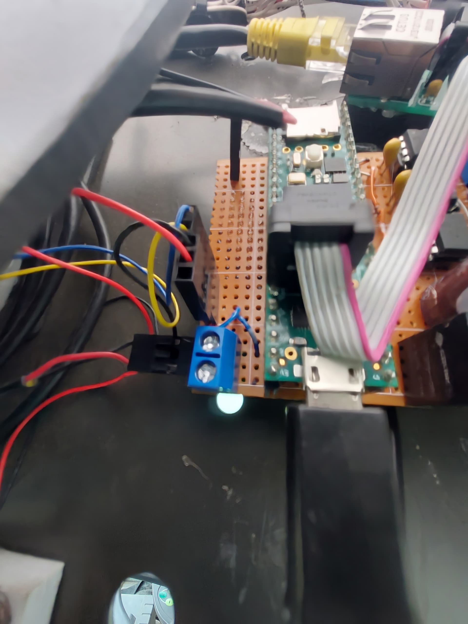
Found a very poor later picture showing the ethernet kit and GPS tx/rx coming in top left on the pcb.
1 Like
Yeah, basically just looking at the bus traffic with wireshark and trying to spot the signals. Nasty work ![]()
Thank you for your answer ![]()
Afternoon all
So, bit of a play with my mate’s brand new 6718S MF yesterday. Found the CAN plugs under the floor below command arm, X183, X184 and X888. Using X183 as no sign of X230, tho I suspect if I’d dug around a bit more it might be in there. Using CANhacker, I was able to grab everything and in comparing the code with @CommonRail 's project 3, I spotted 0x0CAC1C13 was in there. Nice!
However, when I loaded the Massey_CAN_DisplayAC_V2.ino, it found nothing. I was using the canhacker.ino to speak to it and it was picking everything up just fine and lines like this were evident (this is my conversion for display btw, I wrote a powershell script to label everything up nicely).
“0CAC1C13”,“44032”,“24”,“7D”,“3D”,“FF”,“FF”,“FF”,“FF”,“FF”
From the code above, 24/7D will be the curveCommand, and 3D (dec 61, bin 111101) the switch state - but that didn’t co-incide with the code in the INO which mentions 20 (10100), 16 (10000), 0 and 80 (1010000). Hmmm - that doesn’t seem to make sense?
So, the questions are - how come when I loaded the filter code, I got nothing at all (but the things I’m supposedly filtering on showed up just fine in canhacker) and how come I have an apparently invalid value for the valve status?
I noted the CS pin number might possibly have to be changed from 10 to 9, but it’s 10 in canhacker and works fine, I tested and that’s the pin that’s wired. It says it’s INITing OK.
Also, I’m on a dual-micro AIO board here - no CANBUS support that I can see. My MCP 2515s I’m using on the Nano are out of the game as they’re 5V, which would upset the Teensy? The micro board I have is v2.4 and still has the CAN headers on which go up to where the ADC is for SCL1/SDA1, so…? Doesn’t look like C232838 is fitted to the board, so guessing that’s an issue.
Any suggestions? Thanks!
EDIT: annnnd having posted all that, I remembered I’d edited the canhacker clock to sync at 8mhz instead of 16. When canhacker connected at 16, I got nothing. I really hope that’s all it is…! Grateful for any thoughts on the other stuff tho!
Hi,
Is it possible to make the PANDA setup work with CAN-PCB?
And how do you need to connect the f9p to make it work?
Best regards.
Yes, it works
I connected the f9p with the pixhawk connector to Tony’s Can PCB
rx1 from the pixhawk to tx3 of the CAN PCB, tx1 from Pixhawk to rx3 of the PCB. I also connected 5V and GND.
As ntrip Client I use a Teltonika TRB142 which is connected to UART2 of the f9p
In the CAN Service tool from Tony I selected Panda @ 460800 baud.
You must also feed 3.3v to SimpleRTK2B’s IOref.
Or does the Pixhawk take care of that?
I didn’t was aware Tony’s firmware was able to do PANDA, thought it only forward GGA/VTG.
The rx and tx of the pixhawk are at 3.3V…that was one reason why i took the pixhawk. 5V is also not required if you Power the f9p by another way.
Panda ist new to Tonys Firmware since the beginning of the year
1 Like
I messaged Tony and he said just to connect f9p with the rx and tx on the PCB and it should work.
That Pixhawk connector is directly connected to the F9P not the level shifters as the PCB pins are connected to.
We updated the code a while back to do both GPS setups (plain forwarding or Panda)
1 Like
Hey I’m new to AOG, and decided to jump right into steering with canbus. I have a Massey 6616 that is autosteer ready, so I ordered one of the canbus shields for arduino and set it up to show all can messages. That works beautifully, I connected to the green and yellow wires on the right side of the seat and the serial monitor ran a steady stream of numbers. My problem is that I can’t seem to find the steering bus. When I press the auto steer button on the side post, the green light comes on, but no numbers with an “AC” show up in the terminal. Does this mean the WAS is not sending a signal? I tried all the connectors I could find, both beside the seat and also took the cover off the right hand post and tried a few there. Reading through this topic, I see various connectors mentioned, X183, X184, X230 etc. I cannot find any of those in this tractor. Any help would be much appreciated.
Edit: I did find X230 after all. The wires are indeed yellow and green, but they also have stripes of red and orange. I saw a few other posts on here from people with the same problem, so hopefully this can help someone.
1 Like
Hi Ken
I’m using X183 (the one furthest from the seat). When you lift the cover from right hand side driver’s floor, you should see 3 - X188 is at the bottom (engine/transmission), X184 is top-right (I think this is hydraulics, joysticks etc) and X183 (top-left) is where you’ll get the CANBUS info. All this is on a 7718S and a 7724.
You might find this useful too: https://discourse.agopengps.co/m/uploads/short-url/rVnUnDyNSRp64lkfAOMPgvfv40T.pdf
is it possible to use original john deere enable steer button for aog steering on and off? and with machine control the scv operated or the itec button on / off so that I can set the itec myself. don’t know if this goes via canbus or via another way, have the gen 4 command center
[image]