Hi
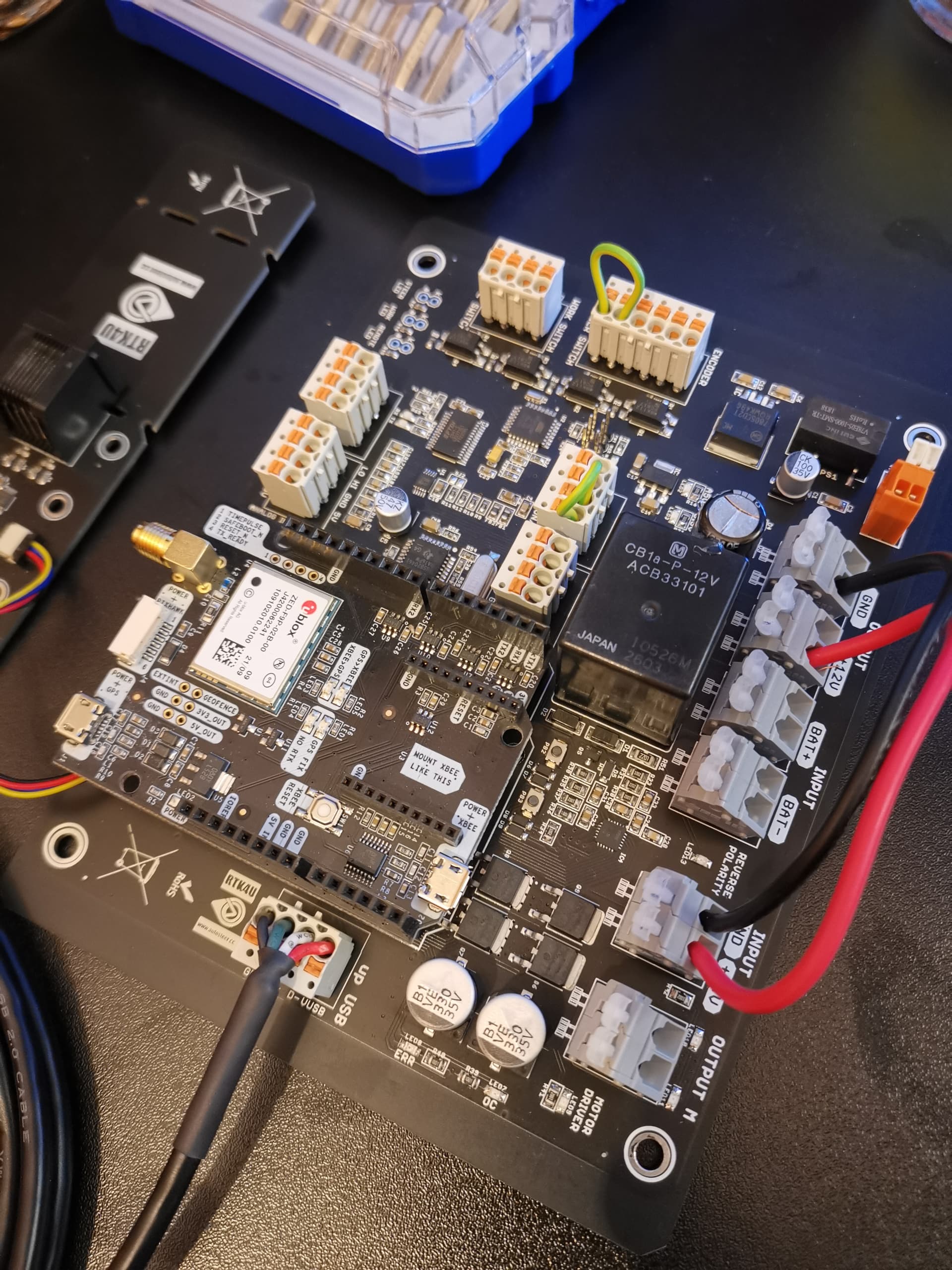
The f9p is in a printed box that is mounted to a steel plate that holds tractors other computers (also the one where I stole the dumb valve pin). This is located behind the drivers seat near the cabin fan. I used guality double sided tape to mount this box to the plate. I’ll try to add a picture and files for this box to fist post.
The usb cable is just a regular cable that I simply cut in two peaces and soldered female drc pins to other half and male drc pins to the other… then just assembled those pins to the drc connector so that they will meet each other when its connected.
Yes. Or at least I have wired the WAS through this 40 pin connector X716. It’s found in pins 9, 18 and 38
For some reason it’s not shown on this schematic that charlesdego has made… I’v understood that he has done it the same way. Is that right @charlesdego?
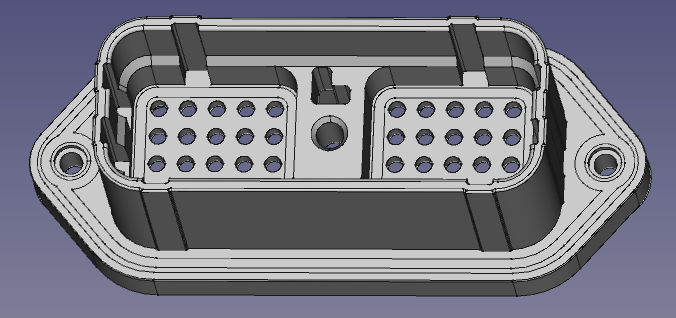
So I noticed on the mouser page they had a link to a CAD step file for the 40 pin bulkhead receptacle. Here’s a prototype of a 3D printable version of the plug that might come in handy for some. I modified and simplified the step file mouser had provided, so it’s close to the right dimensions but I haven’t yet accounted for tolerances. The idea is to push the pins through the holes and epoxy them in place on the back side once everything is wired.
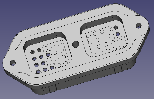
Above image still has all the holes but I decided to plug unused ones:
After I check the tolerances I’ll post the step and stl files here. Any way we could get the forum to allow stl and stp files to be posted?
Receptacle test fit and it fit perfectly. It’s designed to use the recommended pins (posted above), or I think if you had 20 guage Deutsch DTM male pins they would work too. Pin size is about 1 mm, the hole you press them through is about 2mm (might need to be opened up with a drill bit). After the wires with their pins are pushed through, some epoxy would hold them in I think.
I put a zip file with the stl and FreeCAD models here:
Would recommend PETG, but PLA is probably alright depending on where you put it in the cab.
If you 3d print the plug, let me know if I got the correct holes plugged. I think I did. I double checked it even. But could have still got it wrong! The center hole is sized so that you can thread the bolt into it. Seemed to go okay. Although you could drill it out and push a brass threaded insert into it. Definitely print with supports.
On Mouser I noticed that the real receptacle plug is not in stock and the lead time is 27 weeks!
Due to lack of time (but mostly of knowledge!) I got a pre made board and kit from Andreas. First issue is integration with tractor hydraulics, would I be correct in thinking that pin 10 and 20 in the drc connector would align with Output M on my board?
I also have a kit like yours and certainly the M output is the equivalent to the citron of pbc v2, to go to the valves, pins 10 and 20 of the Deutch connector. The problem I found is that A0 in this kit is for the angle sensor and the pressure sensor cannot be connected to this pin as indicated now in AOG v5
I still don’t have the system working because the deutch connector came to me this week. The idea is to take the 3187 that is disconnected from the rear column switch to activate a relay that supplies 12v from the cabin plug to the 3168 cable so that it powers the valve only when the button is activated.