I would like to install a guidance system in a maxxum, I am thinking of ordering a kaupoimod4.1 pcb. I read a lot of posts to understand how it works.
how did you connect the lift information to get the coloring?
In this project I don’t have the automatic painting wired.
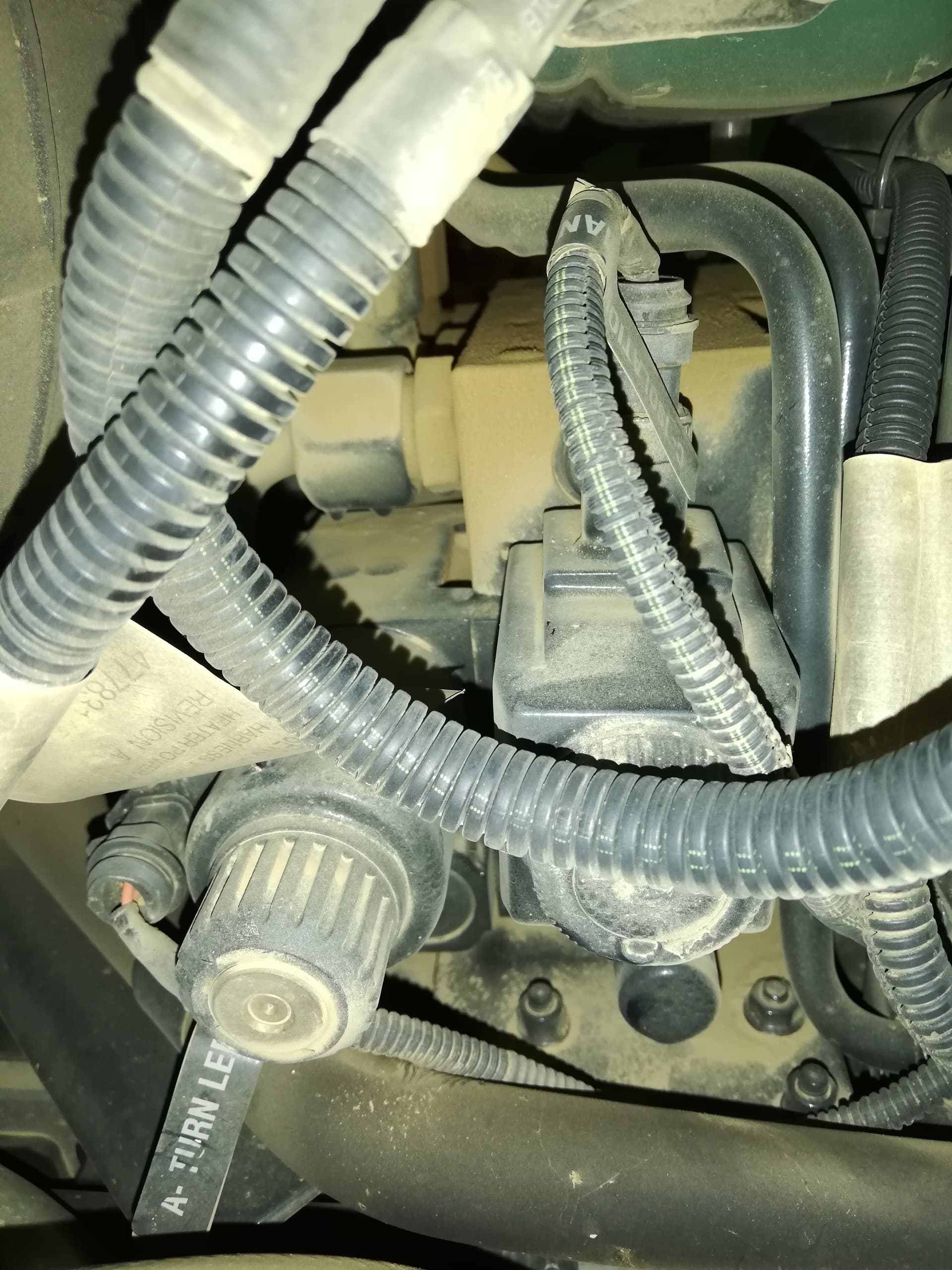
That being said I have done it later using the 7-pin implement connector.
Pin 4 does give you a work signal. Wire that to your pcb of choise.
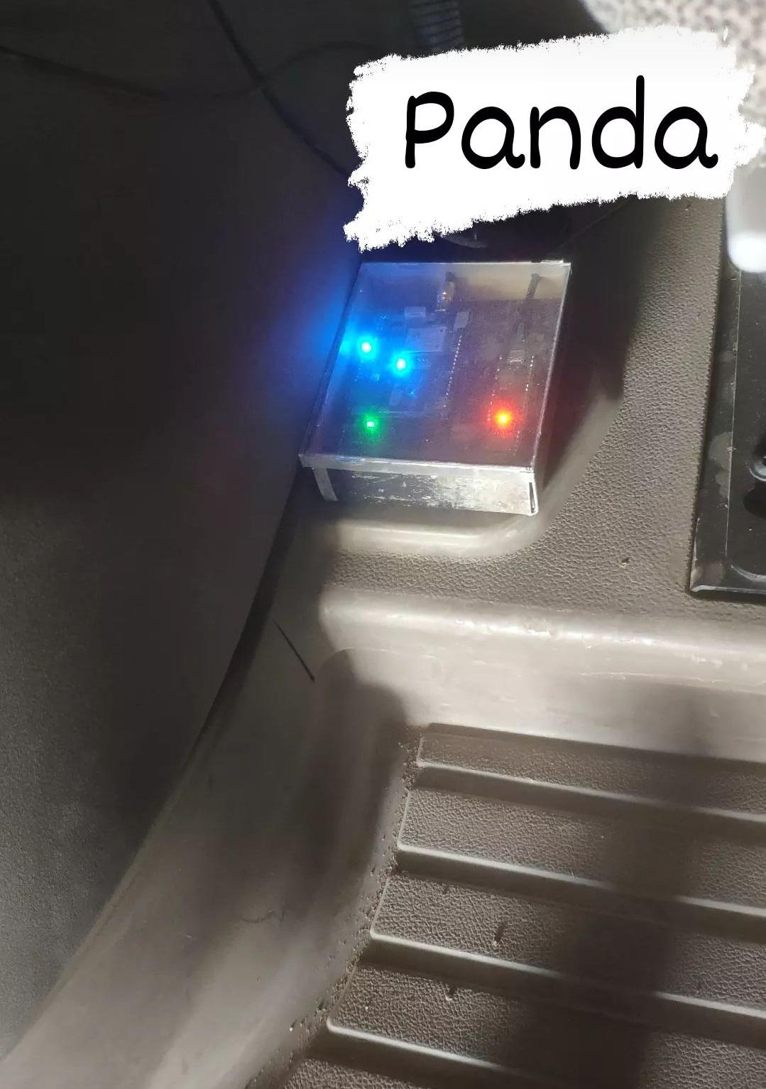
Speaking of PCB, you should really consider the AIO boards instead of Kaupoi as it doesn’t have the panda.
Personally I’m running AIO micro board with single GPS and panda in my puma nowadays.
1 Like
I wanted to order a kaupoi but I’m not sure of anything,
for example which AIO pcb
Is your tractor autosteer ready? The kaupoi cannot steer over can bus.
My tractor is not canbus, I would like advice on the best PCB, I am taking everyone’s opinions.
Have you got a steering valve? Show pictures of it pls
Would go for PCB 4.1 with cytron
I advise you to put the AIO board in any of its versions. Currently my puma is controlled by the V2 PCB placed in the predestined place for the OEM autosteer and the panda plate on the floor on the right side of the seat. With the AIO you would have everything in the same place, hidden and professional.
1 Like
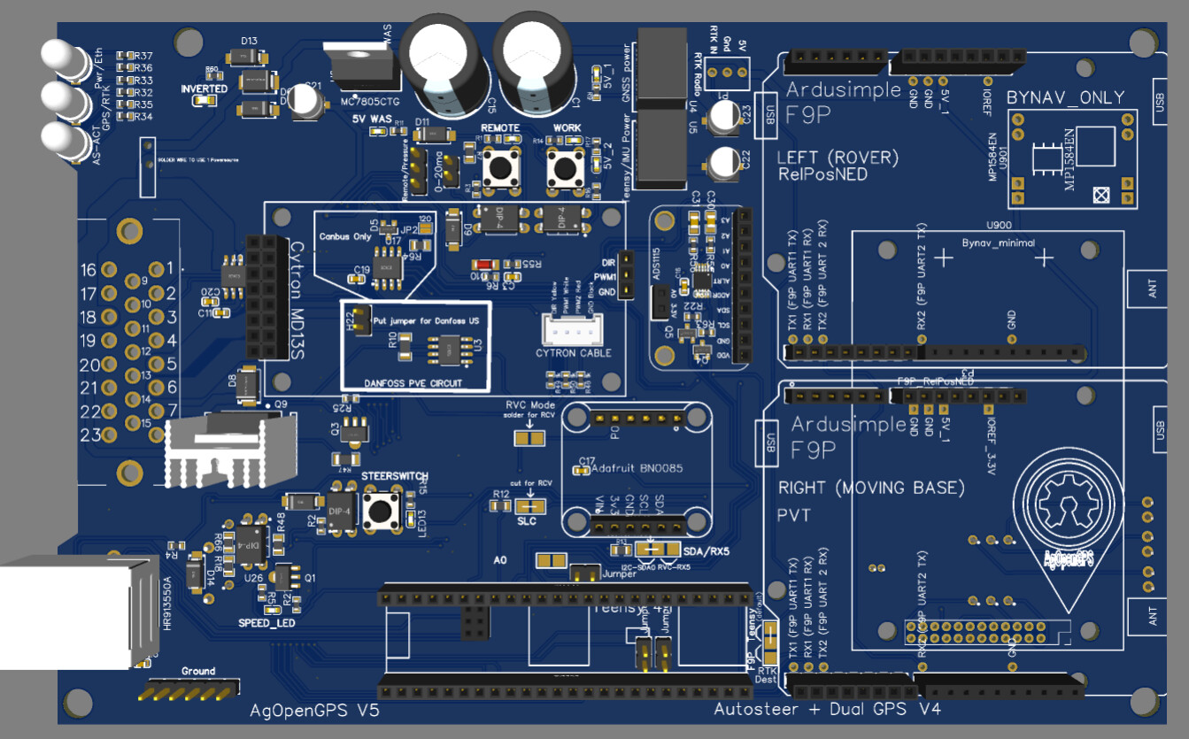
That one ?
I would have preferred tht components to be able to weld them myself. I will ask jlcpcb to weld them.
It’s your choice😊
That AIO board is for normal f9p. I’m not sure if it fits under the tractors cover. I do use the AIO micro version that uses f9p micros for smaller form factor.
All I’m recommending is to make system that uses UPD as a connection to computer and if your going with single antenna use a teenesy and panda software for better accuracy of steering.
You can achieve these with Kaupoi board by adding an UPD module for the arduino and having a seperate gps module where you have f9p and teenesy also connected with UPD.
I also want to add that the kaupoi board has better grounding possibilities for the case wiring.
The case wiring harness has ground wires from each device coming towards the PCB, but the AIO board are clearly designed with a mindset of grounding devices outside of pcb and therefore there is a need for an external ground point.
Hope that makes sense😅
Thank you for all this clarification. I will measure the size and order an AIO card.
I have to pay attention to the orientation of the bno and therefore the PCB, right?
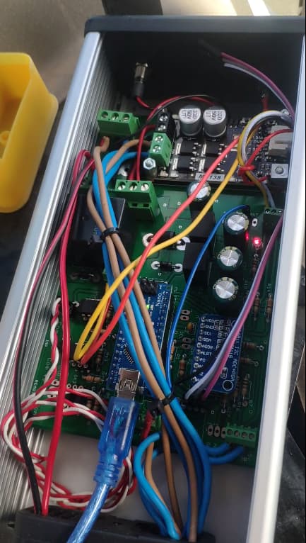
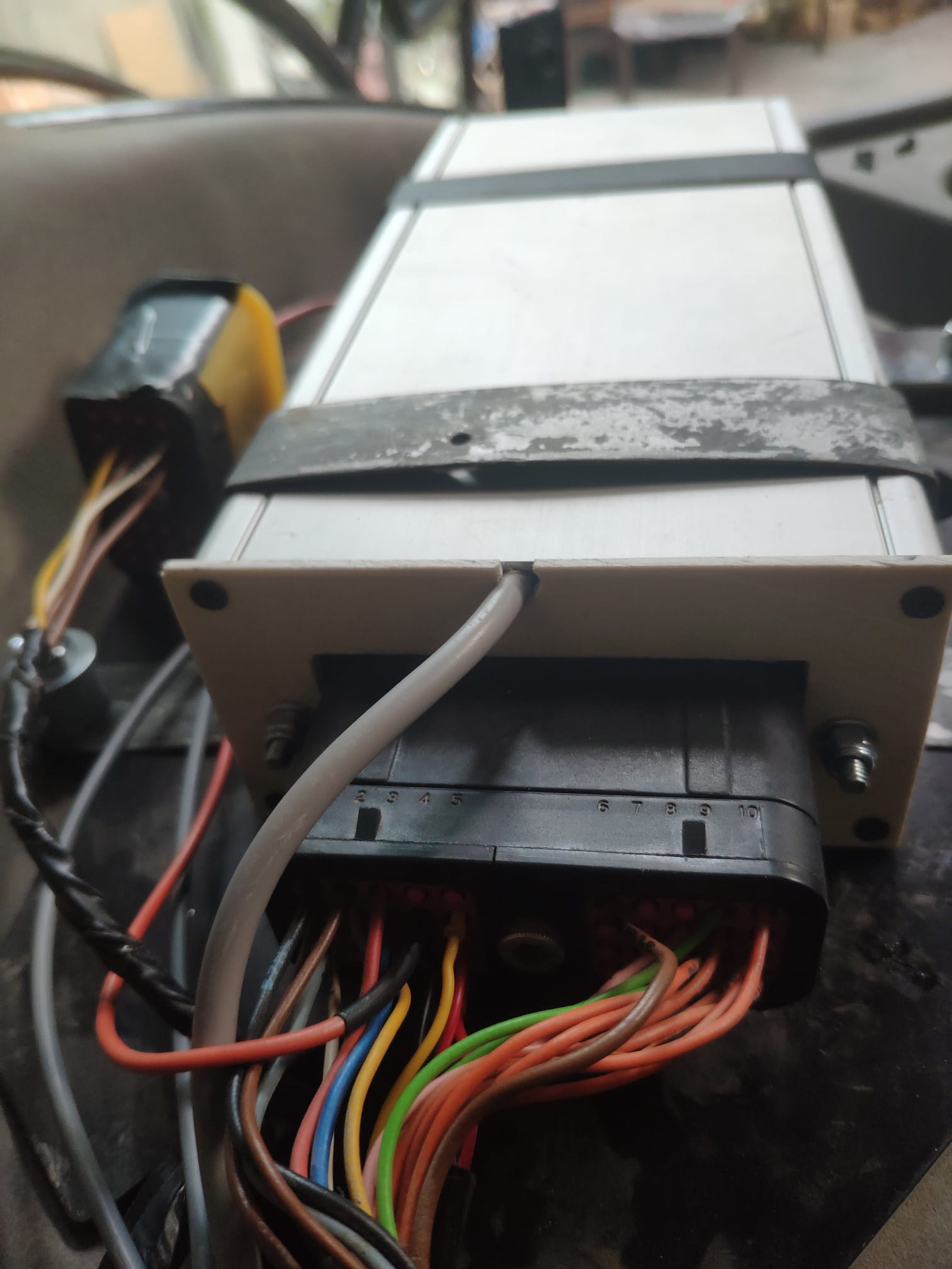
Any experiences with the box? ABS or aluminum?
Yes, that is correct. You can change and invert the BNO axis of measurment with software(if I remember correctly), but it has to have some side facing forward, no 45 degree mountings.
As far as enclosure goes, the material doesn’t really matter. Use what you find cool.![]()
I’v actually been thinking about this, as the original navcontroller seems to be mounted 45 degrees to direction of travel… could trimple be using two axis of imu and fuse them for some benefit?
No idea about the Timble box but even if they did use two imus, why would they install the components that way instead of installing the components in a 45 degree angle, allowing the box being installed “one side straight ahead”?
I’ve always installed my AOG imu as each axis is named but wouldn’t any rotation be fine for heading (as it is fused with GPS), just roll measurement would go wrong? Is the Trimble box also doing roll measurements?
Yeah, thats true about the orientation on trimple. Silly me. I guess they have roll measurement in there as the stand is made to be perfectly horizontal.
And about orienting the AOG PCB you are also very much correct.
1 Like
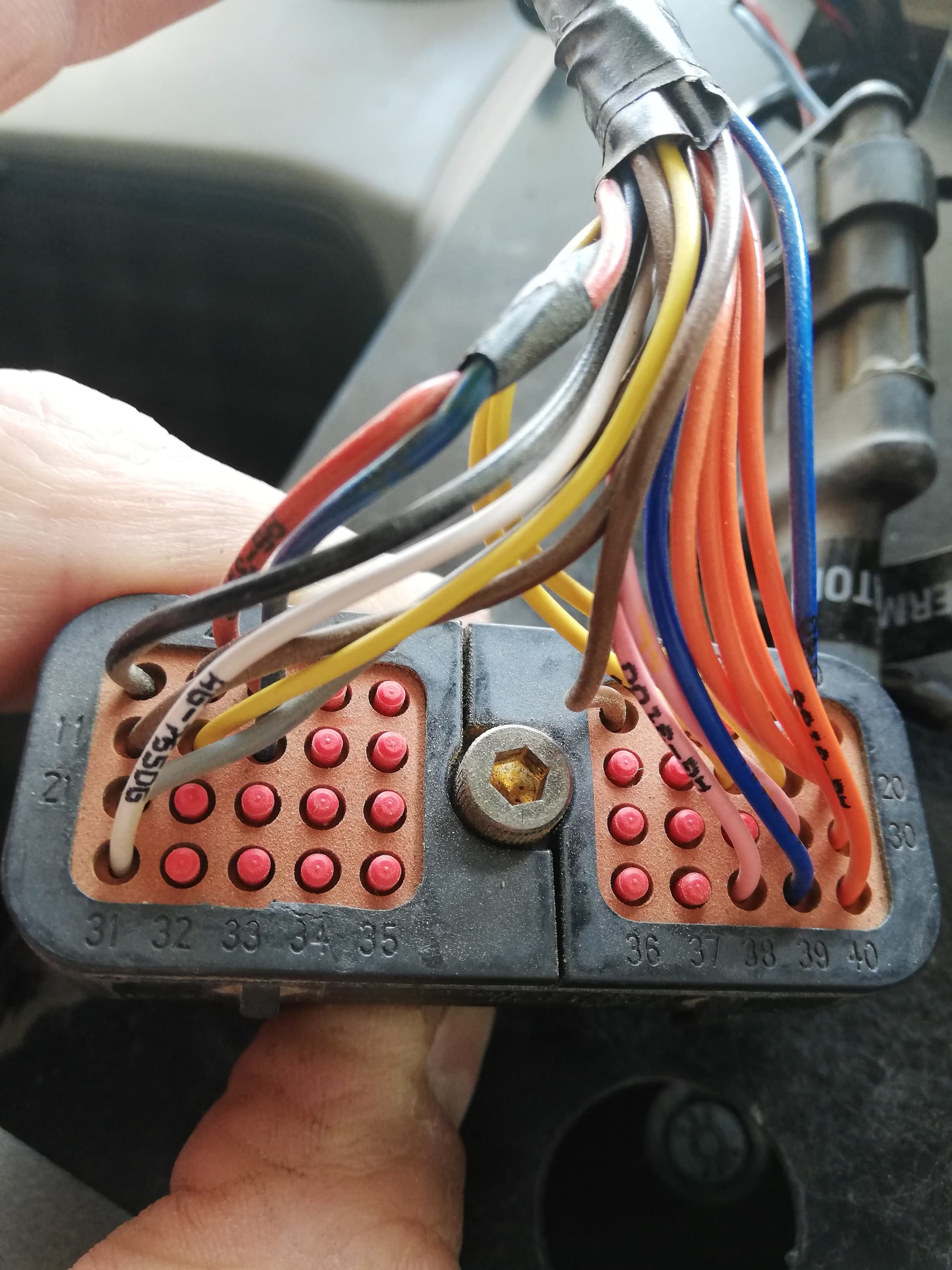
Hi, I got this working today on my puma, I had trouble finding the dump valve wire behind the seat, the ecu looks different to the document above so I ended up running a wire through the door to the valve for now. All the plugs on the ecu are labeled cn8 etc. Any ideas? Thanks
On the nh t6 175 i made AOG for 3 years ago, i didn’t find the wire behind the seat. But it comes with the autosteer loom to the plugs and the 3 relays behind cover at your right knee. One for cut off, the 2 other for right and left direction.
1 Like