Compact Teensy single GPS hat for autosteer PCB

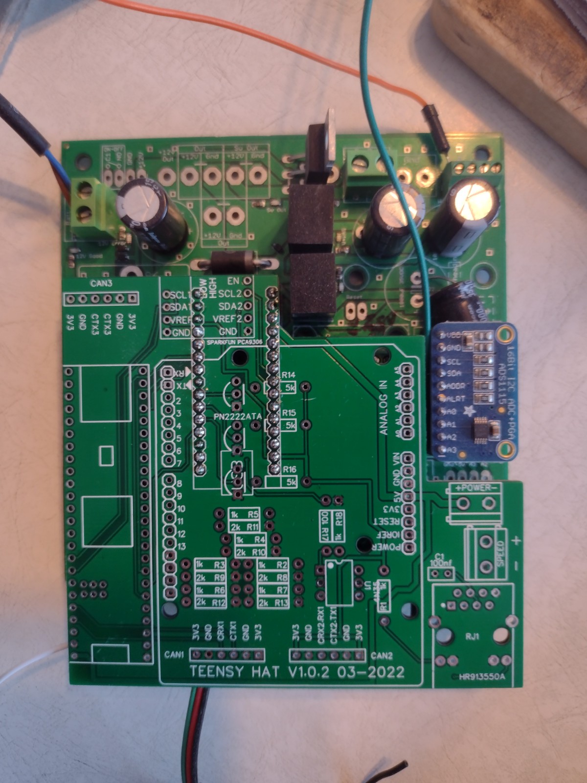
I decided to draw a PCB to mount the future all in one Teensy synchronized GPS/IMU +autosteer code to my existing PCB’s.

So it plug in the Arduino heaters and make a compact assembly. It could also be used as GPS only module with correct supply.
I have just a little knowledge in hardware so every comments are welcome if someone see a mistake or have idea to improve design.
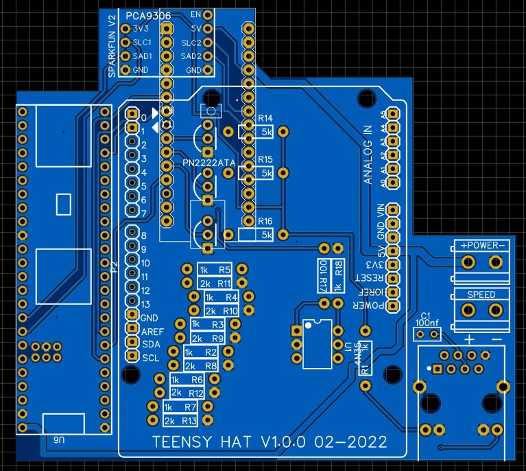
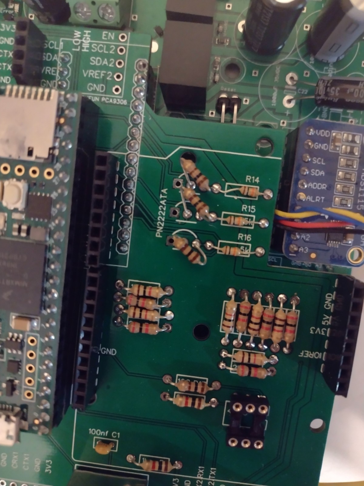
First thing is Teesy run on 3.3V while Autosteer PCB is on 5V. So I put a Sparkfun PCA9306 for the i2c, PN2222 transistors for the input pins STEER, WORK and REMOTE(for my m_elias kaupoi v4 smd boards) and 1k/2k resistors for analog inputs A0,1,2,3,6,7.
It also has a pulse speed output and UDP.

Note: It is designed for KaupoiV4 board without the relay. It will need some raiser with relay or on the official PCB to clear the ADS.

I just saw that my SPARKFUN board pinout seem to be wrong.
Schematic_Teensy GPS autosteer Hat_2022-02-27.pdf (118,4 Ko)


6 Likes

Nice idea.

Might be hard to connect something in the speed output screw terminals.

1 Like

Yeah, you re right, I will move theses.
I will also add one hole aligned with the autosteer PCBs for sturdier mounting.

There something fishi about your pcs 9306. Spelling and pinorder?
https://learn.sparkfun.com/tutorials/pca9306-logic-level-translator-hookup-guide-v2/all

Yeah I saw it while writhing my first post!
I will check that today, I have one somewhere.

I used this on an other board design that arrived a week ago, so I will have at least 2 design for JLCpcb!

Looks great! What about IMU?

It will use the autosteer IMU if connected to it, else I planned to use a 10 cm lead if used in standalone GPS mode.

I could make it a little bigger at the top left and add holes and connections for the adafruit, CMPS.

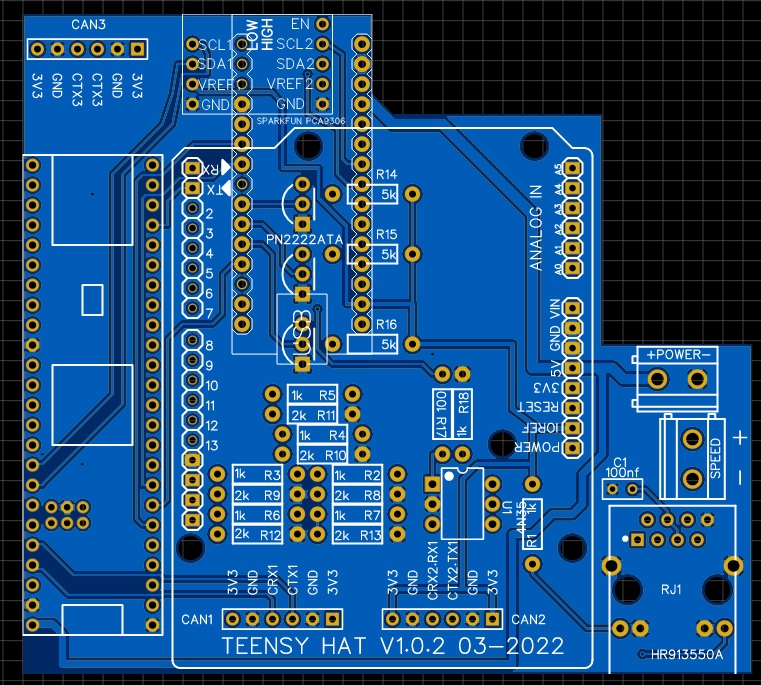
To add CAN capability I will also add 2 or 3 rx,tx,GND,3V connectors. I suppose it is pins 22,23,0,1,30,31 on Teensy?
Is this CAN board or this one enough? Rx and Tx are not on same position on each board :grimacing:
Someone know a good board/chip? To order on Aliexpress? I prefer Digikey, Mouser or Robotshop

I wasn’t thinking about motor controller also. Using auto steer pcb in conjunction with this I see. Thanks great work!

You could just add the footprint for the can transceiver like on the common rail board.

Or like this to be able to change it.
The spacing would be the same

I’m not sure there is a need for the level shifter. When I remember me correctly the i2c Bus is driven by the teensy and not from slaves. I tried a setup with PCB V2, nano33 iot, bno055, mma8451 and ADC for WAS and it was working perfectly. If you check the bno pins there is a 3v3o pin, so there must be a voltage regulator

Ok, I will check this.

@CommonRail do you have a schematic of your TeensyCAN board? Is it all trough hole? I saw little SMD on the picture.

Here is the JSON file for easyeda.

1 Like

Thanks for all yours inputs!
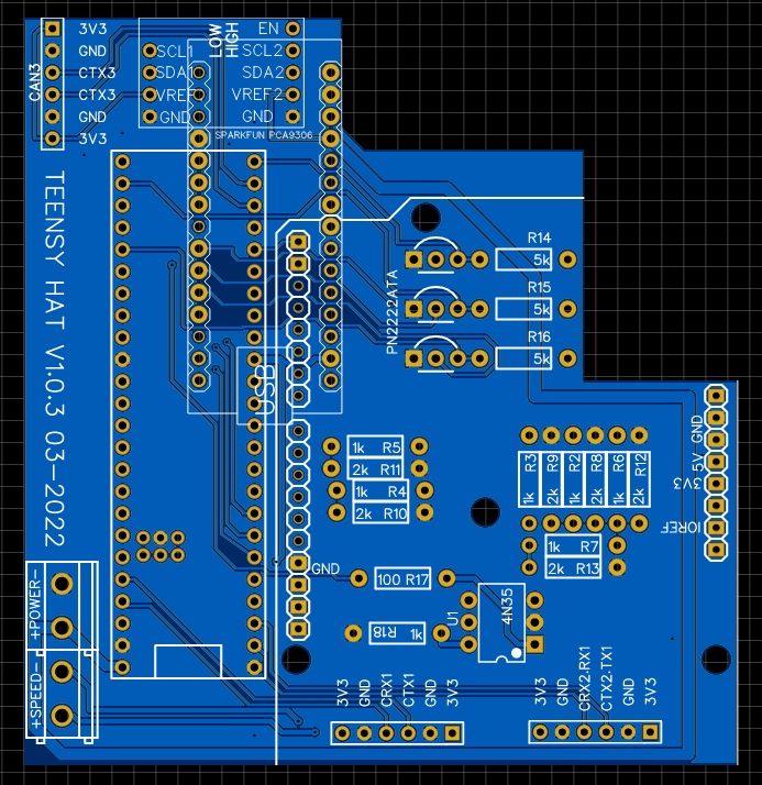
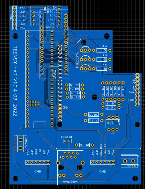
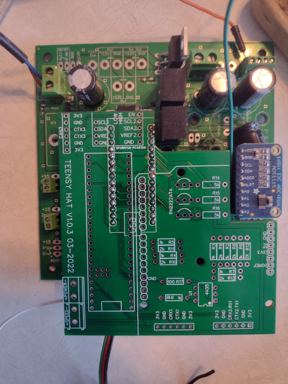
So I have now 3 design I will order(only 2-5$ per design, most is for shipping)

I have only added minimal connection for CAN just to have capability for testing(prototype)
SDA/SCL lines goes directly to autosteer PCB, but pins for PCA6306 are there, just cut the lines on rear of PCB

Design 2: added CAN pins

Design 3: new compact design to clear autosteer input pins (STEER, WORK), without UDP

Design 4: 3+ UDP

So I will have some surplus to give around, shipping should be cheap for Canada/US! :wink:

The boards have arrived
Took 21 days with cheap shipping, cheapest is to order only 5 boards, shipping is then something like 3$

I will test as GPS with PANDA, and will try to build a code for GPS+autosteer later

V1.0.2 compact UDP but switch input are covered

V1.0.3 USB only

V1.0.4 UDP but a little longer

4 Likes

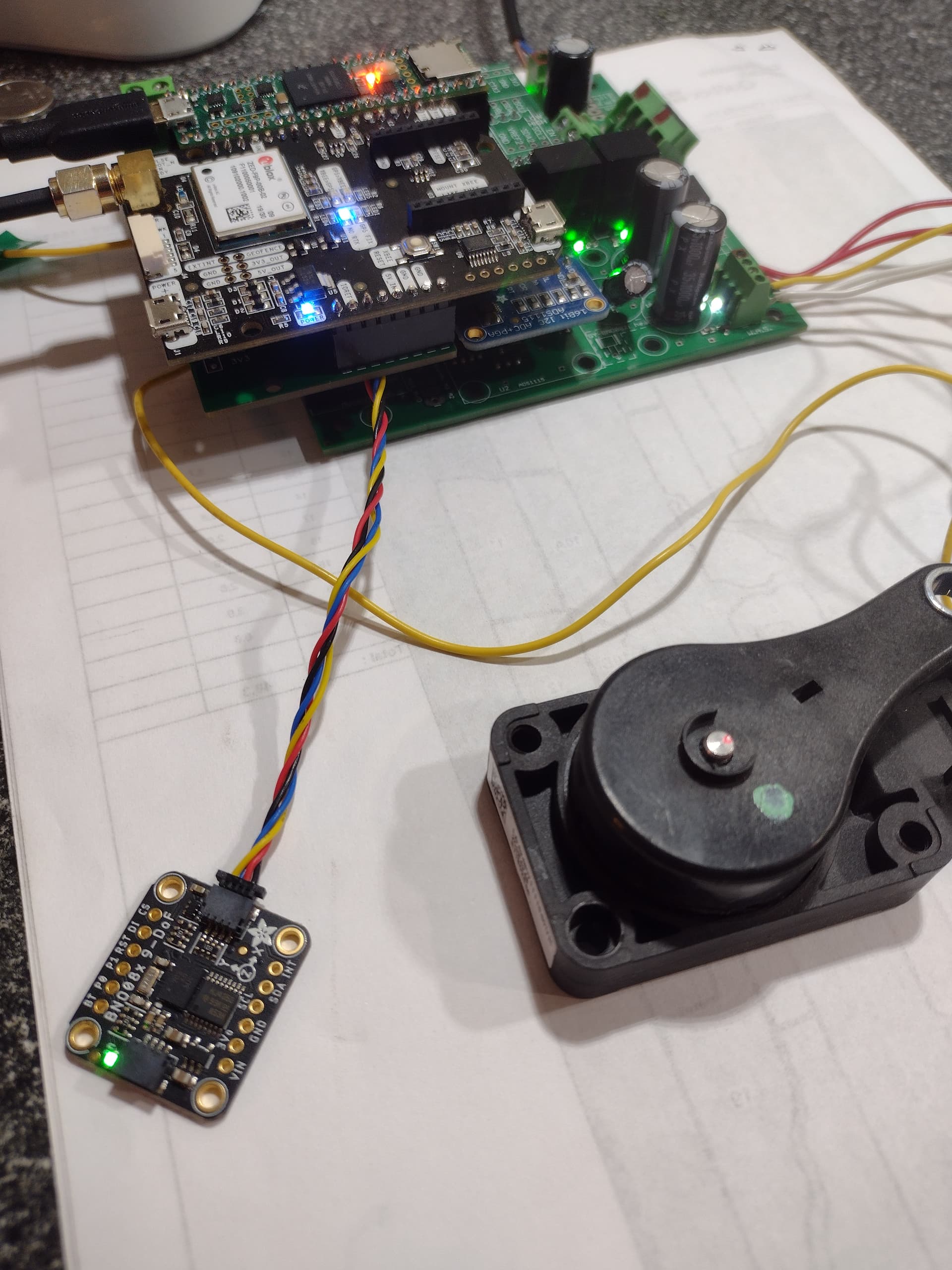
I used the board to send PANDA to AGO and it worked, just took 3 hours before before I figured out my SimbleRTK2B wasn’t sending anything over UART1! :roll_eyes:

Now I want use the Teensy for GPS+autosteer over USB, I think I just have to replace Serial by SerialUSB1 for autosteer and I should have the 2 COM ports.

1 Like

It working on the bench (trough USB) will test in real condition soon.


Edit: 7-04-22 Corrected code
Code:Panda_Autosteer_Teensy_USB_v5_0.zip (37,0 Ko)

EDIT: The transisors on the boards don’t read the switches :unamused:, I think I can mount some resistors in the same holes to make it work.

These boards work as Teensy-Panda but need modifications to be used as autosteer hats.
Geber without UDP:Gerber_AOG PCB_Teensy GPS autosteer Hat VERSION3-NAROW.zip (116,1 Ko)
Next will be to built a code for UDP.
UDP versions(untested):
V1.0.2:Gerber_AOG PCB_Teensy GPS autosteer Hat VERSION2.zip (130,7 Ko)
V1.0.4:Gerber_AOG PCB_Teensy GPS autosteer Hat VERSION4-NAROW_UDP.zip (131,5 Ko)
The full project:Project_Teensy GPS autosteer Hat_2022-03-02_23-22-22.zip (709,7 Ko)

8 Likes

hello Pat

i like this concept for old board

did you upgrade this project ?

His concept works.
I used his schematics to rebuild a pcbv2 board to work with teensy 4.1 and the autosteer ino made for the new all in one board.
I cut the traces from ads1115 and added a level shifter to connect ads to teensy.

For the switches, just direct from pcbv2 lines/pins to teensy no resistors, as they connecs to gnd anyway.

For output to pwm and dir, I resoldered 330 ohm resistors to go to the right teensy pins.
(Other pins resoldered and 5 v moved to fit teensy as well)
The bno085 must run on 3.3v so it doesn’t need a level shifter when connected to the teensy.

Also some bird’s nest wiring and a Ethernet kit for the teensy. I bird’s nest wired the F9P as well.

But the hat board would do all that.
Just recheck the SDA SCL and the level shifter. So they are like the current all in one board.

1 Like

no upgrade since last post
I used one hat all summer long.

I don’t use level snifter but should, ads and bno on 5v :grimacing:
also the teensy pinout is maybe not the same as the last official teensy board.

Remember: The transisors on the boards don’t read the switches :unamused:, mount some resistors in the same holes to make it work.


1 Like

Hi Pat,

did you get this to work via Ethernet? I see the Antenna and IMU, but steer is not visible for AOG.
I’m using the PCB v2.0 + Teensy Hat V4
image

Thank you,

JB