I ask myself several questions about the use of the following elements:
the “remote” connector 2) what function?
what function does the “analog in” function have?
thank you for your answers
I don’t know why it’s called REMOTE, but it’s an interrupt input to turn off autosteer. The analog inputs are for other extra uses (they can be digital inputs too). I use them to read pressure sensors on my sprayer.
There is code to support an analog pressure sensor on the hydraulic steering setups to sense manual wheel movement which turns off autosteer.
Do you have photos of your assembly or a plan for the remote information and also for the analog in thank you
Gerber and bom files from m_elias
It seems files can´t be changed in same post (files from old discourse group)
Change extension to ZIP (remove .pdf)
another try with renamed file.
lvmod210824_smd-leds_mostly-fixed_top_bom.zip.pdf (1.2 KB)
Hello,
have you got some alternative for the following part on your PCB v4.1?
BTS442E2BKSA1-ND
Because you cannot buy such a part.
thx
Marcus
I think that is a typo. It think it’s supposed to be 422.
Oh Sorry, that is correct, but you cannot order it anyway.
Do there exist some alternative?
Correct part number is BTS442E2. It’s available at AliExpress. Don’t know any alternatives.
I am making connection diagrams to include in the documentation, and I have the doubt if this is correct for the Chinese version and the sparkfun version of the Bno08x, they need 3V, not like the adafuit that has a regulator.
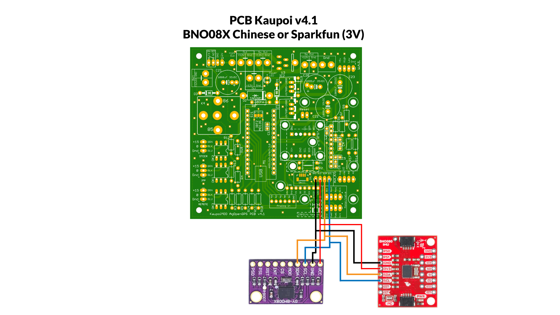
For sparkfun you can always use the QWIIC connector.
3 Likes
I think that is correct.
As a reminder, resistors R1 and R2 need to be soldered to pcb.
I have been using Brian’s original V2 board, but was wondering if the KaupoiMOD PCBv4 is better? What is different other than layout, does it have any added features that the original v2 board does not have? planning on building more boards and would like to keep up with needed changes but if nothing other than layout, i will use the blank v2 boards I have.
Also is there a PCB board for the dual antenna? I thought I seen some place that there was one built to mount the two f9p’s and the esp, if someone could direct me to the file it would be appreciated.
Similar board but smaller in size, with BNO085 Adafruit slot and CMPS14 slot, ready to use on V5.
1 Like
It has the BTS chip onboard to switch higher 12v loads on/off with auto-steer on/off. It also has a connection header for a Canbus board and I think it breaks out more of the extra leftover IO from the Nano.
I also modified KaupoiMod v4, added A6 & A7, changed many resistors to smt and added indicator LEDs. JLCPCB can assemble the smt parts.
2 Likes
@Kaupoi A bunch och PCBs are on the way from china at this moment. I’m about to order all the small parts from Digi key now.
One question though… The DC/DC-converter VX7805-1000 is out… Can it be replaced with a V7805-1000? https://www.digikey.se/product-detail/en/V7805-1000/102-1715-ND/1828608?itemSeq=388249903
Specs are the same but are pin 2 and 3 reversed on VX7805?
For me Digikey says vx7805 “474 in stock”. https://www.digikey.se/en/products/detail/cui-inc/VX7805-1000/7350292
Don’t know if v7805 is suitable.
Wow, magic fingers. ![]() When I checked it said delivery at end of mars…
When I checked it said delivery at end of mars…
Optocoupler 4N33 is replaceable with 4N32?
This doc mention no diference, but actualy the other in is diferent manufacturer: 4N32IS-ND