Did some testing today. With autosteering off, when +12V power supply to MD13S is not connected, but GND is, MD13S is braking about 50% force (by fingertip feeling) comparing if it has +12V ang GND supply connected. Directional led and ERR led are also on if turning motor by hand when +12V not connected.
I also tested how much the BTS442 heats up if the motor is braked to a standstill. I held motor by hand and did not let it spin at all and BTS442 got really hot in few seconds. I think it’s good to have a heatsink on it.

It is not understandable to me why we use the BTS422E2 chip, which was produced in the 90s.
Ordering this system from China is almost a miracle for it to work properly. Not to mention its price.
Not to mention how long it takes to get the thing shipped here.
Is there a better solution ?
I propose systems that are available in good quantities, the availability of electronic wholesalers is substantial.
Unfortunately, you would have to make small pcb modifications or add an overlay from smd to tht transition, for people who already have 4.1.
Please do not take offense at me for this list or the changes. KaupoiMod considers a very good project for AOG, which I support.
As for me, it was an unfortunate move to reach for a system that does not exist in the age of wholesalers and even borders on a miracle to get it. Looking at the domestic market, I was able to unearth prehistoric finds in the warehouse I supply.
For the whole of Poland, there are 18 pieces of this system in stock.
Below is a list of solutions that we can use or discuss.
BTF3050TE https://www.tme.eu/Document/74a656bad9167a9e1d740c8d48aa680c/BTF3050TE.pdf
BTS141TCBUMA1 https://www.tme.eu/Document/c16452c2fb51809a63bc999d3f430510/BTS141TC.pdf
BTS3080TF https://www.tme.eu/Document/83df2405c9dae63b083d088025e3f9b7/BTS3080TF.pdf
BTS428L2 https://www.tme.eu/Document/80044ff0b5393e7af862ee642180a11f/BTS428L2.pdf Buy Electronic Components Online - LCSC Electronics
BTS6143D https://www.tme.eu/Document/e322d6ff87f5790376335abca4d2e610/BTS6143D.pdf
BTS443P https://www.tme.eu/Document/1c4989800d27c4d45c338caad0b80446/BTS443P_DS_v10.pdf
ITS428L2 https://www.tme.eu/Document/625f94d710fc61e281ad5542340d54a9/ITS428L2.pdf
BTS6163D BTS6163D Infineon Technologies | C534821 - LCSC Electronics
BTS443P https://datasheet.lcsc.com/lcsc/Infineon-Technologies-BTS443P_C69856.pdf
BTS462TATMA1 https://datasheet.lcsc.com/lcsc/Infineon-Technologies-BTS462TATMA1_C127050.pdf
BTS3160D https://datasheet.lcsc.com/lcsc/Infineon-Technologies-BTS3160D_C112627.pdf
1 Like
Good suggestions!
However, I would like to keep the pcb made of THT components as much as possible, so that even a beginner can easily assemble it.
How about Benjamin’s suggestion?
Or just learn how to install SMD components …
Note that this BTS422E2 chip is out of production since infenion bought a Siemens.
The availability problem is a serious threat to the development of this PCB platform.
Note that the correct part number is BTS442E2, not BTS422E2. 
I found some 422’s and ordered them before I knew that the 442 was the correct number. Will the 422 work also ? I am powering a Danfoss valve, way under 1 amp.
1 Like
my mistake as to the marking of the BTS element (mosfet).
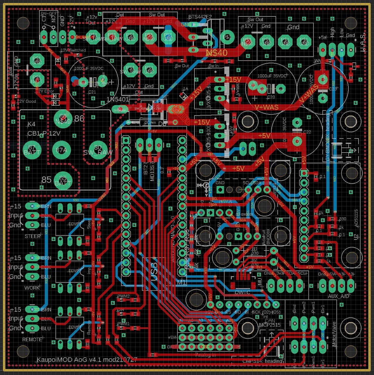
My CAN valve setup on this PCB, thanks @Kaupoi for delivery from local stock 
Used the chinese MCP2515 with connectors resoldered on the backside and long risers so it sits on top of the board. Bno085 orientation seems to be 90 deg off from ino default, couldnt find the option for roll direction from v5 anymore, so a small ino edit.
2 Likes
Hello I’m new and I’m very interested in aog.I’m after buying my components in order to make mine. I wanted to know if it was possible for this system to handle the row break on a single-seed corn seeding controlled by a mini touch case. If so how? Thank you for your help
Can I request the following changes?
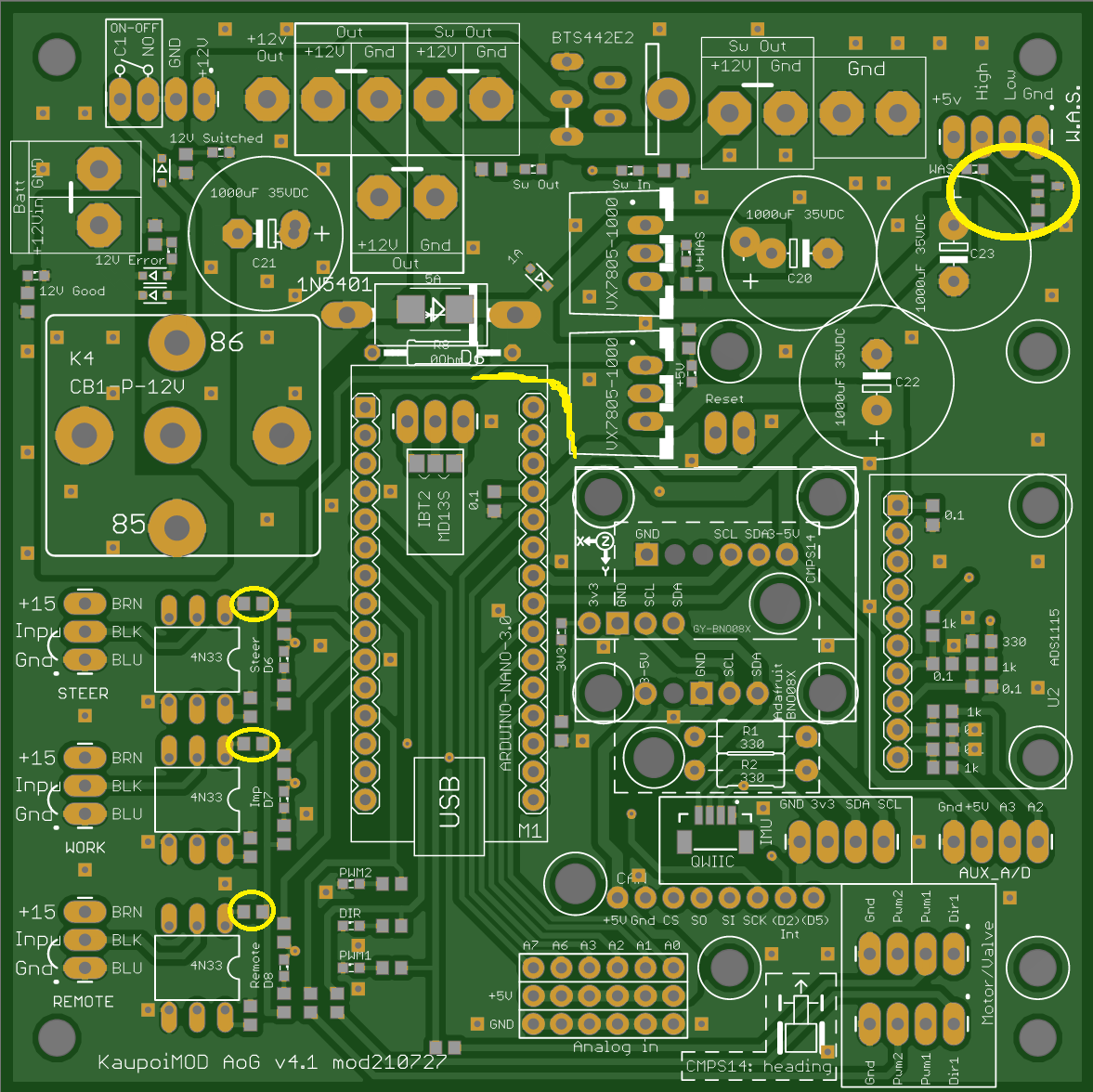
I narrowed the extra analog traces from 32 to 20, should still be plenty of copper for high impedance signals.
I also had to add 100K or higher pull down resistors to pin 6 of my Chinese 4N33 optocouplers, otherwise they turned on from stray voltages somehow. I just added them to the back side of the pcb underneath the 4N33 chips but if you could find room it would be nice to include.
@Kaupoi I could probably generate the files myself too but it’s been so long I fear I will forget something import and waste a production run.
1 Like
Where did you guys order your PCBs from? Any particular hangups to watch out for?
From JLCPCB
So amazing cheap and fast (from China).
Very uncomplicated. Just upload, click next next next and that’s it
2 Likes
@Kaupoi I’m wanting to order PCBs ASAP, do you want to make my requested changes or should I attempt to generate my own gerbers?
I’m not able to do the changes until after the harvest season, sorry. But definitelly will look in to it after harvest.
I think I almost have it finalized. I’ve added connections for my GY-BNO08X which uses two of the Adafruit BNO’s existing mounting holes and rearranged the three IMUs’ pin labels so that they’re all legible. Now I have to figure out how to generate the gerbers for JLCPCB, thankfully they have a guide for that.
This is what I ordered from JLCPCB, should arrive this week. Thanks for the pcb design. Here’s a list of my changes:
- Expanded analog input header to include a6 & a7, with +5V & GND for each
- Added GY-BNO08X device (uses two of Adafruit BNO’s mounting holes), rearranged IMU pin labels
- Added 4n33 pull-down resistors (p6 to gnd)
- Added through hole jumper pins for BTS Cytron/IBT2 input jumper
- Added smt LEDs/resistors for 12V in, 12V out, V+WAS, +5V, +3.3V, Opto outputs, PWM1/2/Dir,
- Added diode to prevent reserve polarity on 12V input (relay coil only turns on with correct polarity)
- Changed ADS capacitors & resistors to smt
2 Likes
Update
Here are the files for a mostly fixed version that I modified. The WAS input LED, resistor and transistor aren’t tuned correctly yet but WAS input is working. The LEDs should be a more reasonable brightness and opto-coupler inputs are working too.
mod210824_smd-leds_mostly-fixed.pdf (75.4 KB)
Change file extension to zip
mod210824_smd-leds_mostly-fixed gerber.zip.pdf (349.2 KB)
mod210824_smd-leds_mostly-fixed_top_bom_cpl.zip.pdf (1.2 KB)
Edit:
Got the original files from m_elias.
Then unzipped, rezipped with windows (send to, and choose zip) renamed to lvmod21… and uploaded here again.
AND it is not enough just to rename the original zip file, that give same problem as above (not available/private)
lvmod210824_smd-leds_mostly-fixed_gerber.zip.pdf (352.6 KB)
lvmod210824_smd-leds_mostly-fixed_top_bom.zip.pdf (1.2 KB)
Previous post
So there are a few needed fixes 
-
The LEDs I added to show what the opto inputs are trying to pull up the Arduino’s inputs to 12volts. The Arduino’s snubbers were able to protect the inputs but the LEDs are lit all the time. So I changed the opto LED source to 5V and lowered their current limiting resistor value to 330 ohm.
-
The WAS input LED’s transistor is not tuned to be in the proper 0-5V range, it only lights up at 0-2V and it’s inverted (brightest at 0V).
-
Most of the LEDs are TOO BLOODY BRIGHT