-I was able to configure the Ublox gps using the accompanying guides (“mitglieder”) and it is working fine.
-I uploaded the “Autosteer_USB_v5_0” support files to the built-in Arduino. And got AgIO coupled to the two built in COM ports (GPS and Arduino). The gps, steer angle and compass/tilt seem to be working fine.
-Now when it comes to the section control it is not clear what steps to undertake.
The support files include also “Machine_USB_v5_0” files that control the section control. But since this is a separate program this is meant to be run on a separate Arduino and not controlled over the I2C bus like in the hardware i am using?
In the “Autosteer_USB_v5_0” files there is also a “autosteerrelays” code, but this is completely commented out and not called in the main program. So this does not seem what i need for the section control.
Edit:
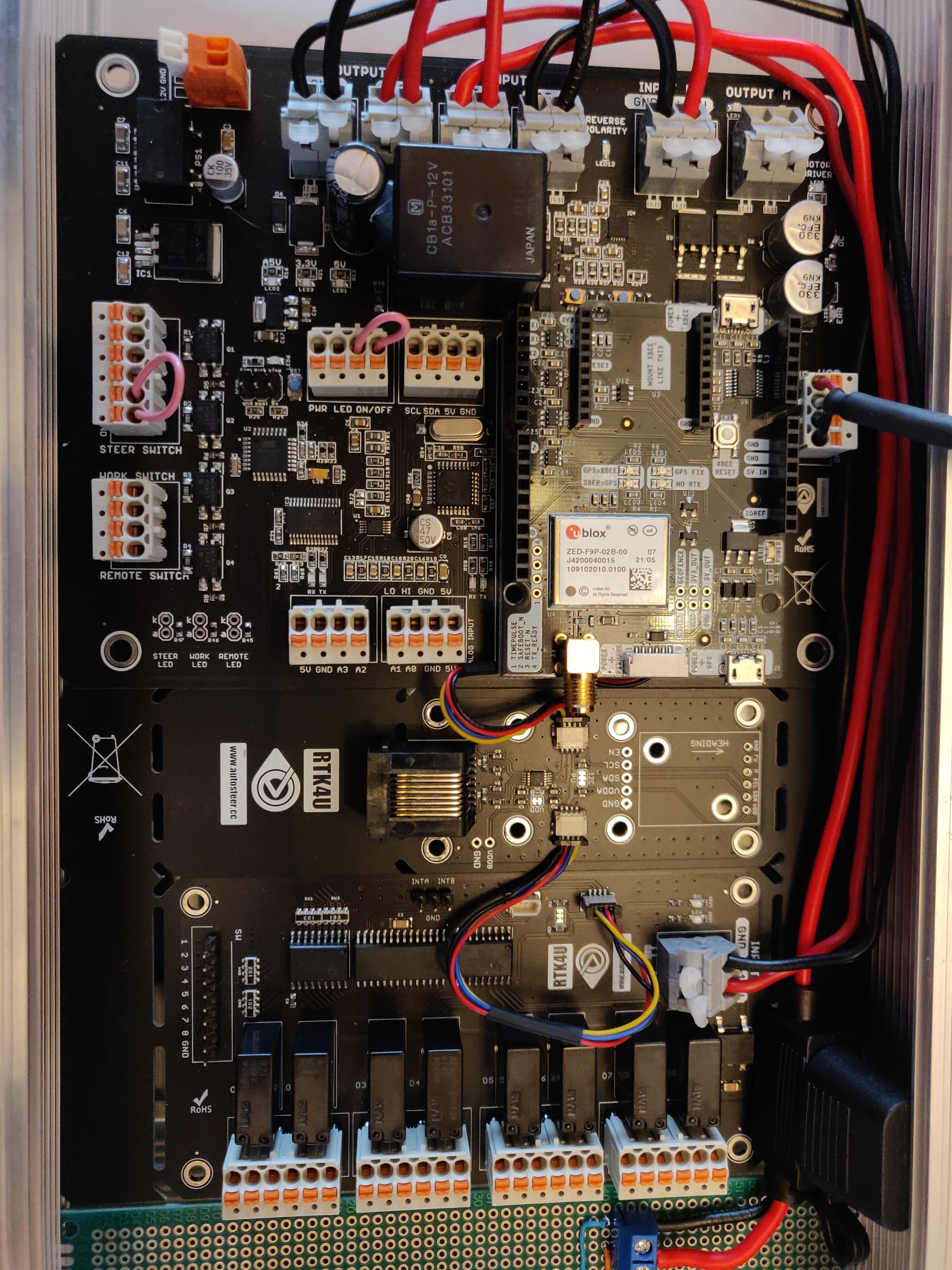
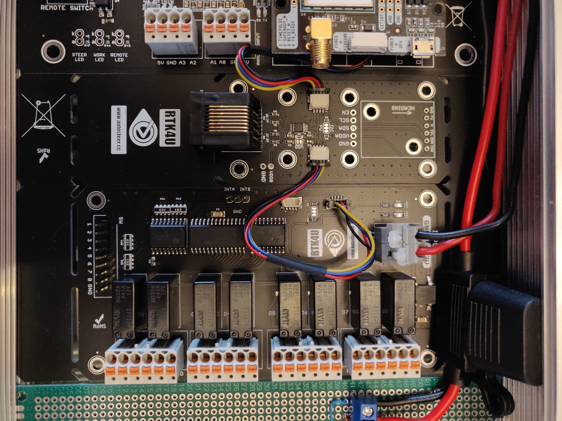
Actually Andreas Ortner does have a 8 relay board in his autosteer shop
This is the one i am using(see pictures in other response). My plan was to buy everything in one place and use components that were supposed to work together. However during setup i am now a bit surprised by the availability of documentation.
Contact Andreas, I don’t know of support for this board in the standard sketches. But he probably has a sketch that works for you.
The relay board is connected to the AutoSteer board, so you need relay switching functionality in Autosteer_USB_v5_0.ino I think
During purchase i did not select the option “16 PCB Konfigurieren”. So i did not expect the Arduino to be already configured and have overwritten it with the generic code from the support files.
Would it be possible to make your sketch available? Or if it already is to point me in the right direction?
Thanks in advance.
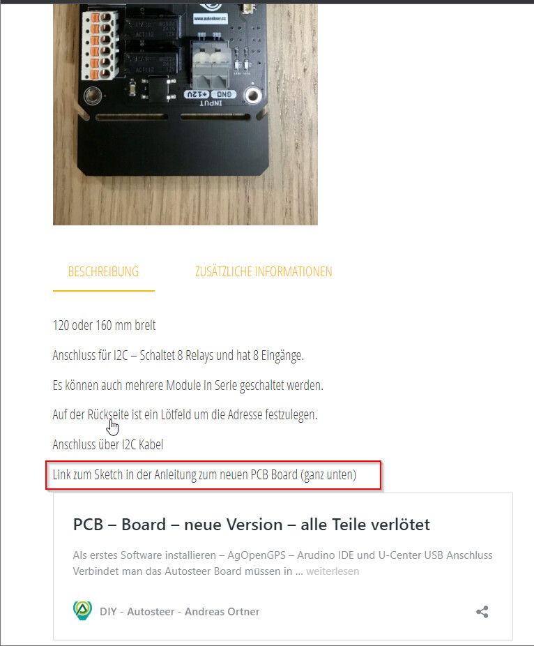
The link on the website leads to the hardware installation guide, no arduino sketch (unless i am overlooking it ). Since andreas is also in on this forum topic i will wait on his reaction.