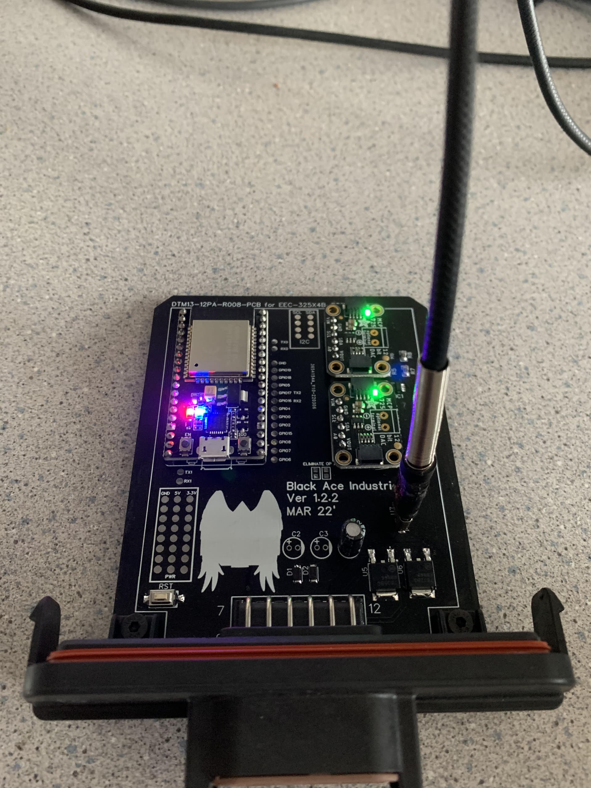
No this is a proportional system it uses a 12 Bit DAC so should be plenty accurate enough to control a prop valve. There is also a PID system running on the grade control that comes up with the analog values and sends them to the DAC’s
ohh my bad then, but that’s okay we have quite a few proportional electric aktuators. so the grade module sends out the recuired volts for the valves? since there needs to be a constant 6V on the spool for it to be in a neutral position and then it goes either lower or higher depending on wich way it’s supposed to go? sorry if im not following along
In the post about cytron are at least 2 ways to convert 5v to control the Danfoss. Or even a pot between 2 1000 ohm resistors (12 v, output to signal and gnd, )
@Bjarke_Kristensen I may make a bit of a diagram today, that will kinda explain how the system works and communicates. May help other to understand how it works and help with questions.
@Larsvest I kinda read through it but didn’t find anything about 5 v signal conversion but I must have missed it. Will re read when I get a have a bit of time.
thanks, that might clear a thing or two up ![]()
Look for posts after 28 here .ino for PCB+MD13S+Danfoss valve - #29 by grabik
Look at the specs for this item, and the alternatives they list at bottom. https://m.nl.aliexpress.com/item/33021792064.html?gatewayAdapt=gloPc2nldMsite&spm=a2g0o.productlist.0.0.1788645fqzeplk&algo_pvid=35b65782-a153-4231-9e87-6be279f14fa0&algo_expid=35b65782-a153-4231-9e87-6be279f14fa0-0&btsid=a915c4d7-f978-4973-82da-aa892c7499bd&ws_ab_test=searchweb0_0,searchweb201602_8,searchweb201603_53
@Larsvest I’m not sure that will work in my situation for two reasons
- I don’t use PWM like AOG just strictly analog voltages
- I don’t have much from room in the enclose I have chosen to put another large module like the one you have suggested.
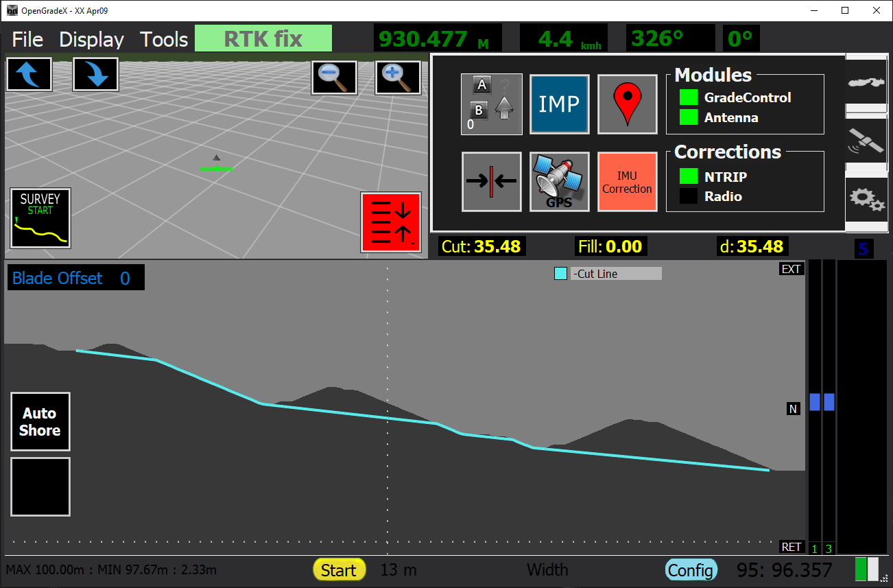
-------------------------------------------------------OPENGRADEX---------------------------------------------------
-SENDS —DATA— Cut Delta, Cut Dir, and AutoStaste to GCM
-SENDS —SETTINGS— PGAin, IGain, DGain, Valve Type, Ret Deadband, Ext deadband to GCM
-RECIEVES —DATA— Auto State, Valve 1 Voltage, Valve 2 Voltage from GCM
-RECIEVES —SYSTEM— Firmware Version from GCM
-RECIEVES —GPS— NMEA to from AM
-RECIEVES —IMU— Roll, Pitch, Yaw to from AM
-RECIEVES —SYSTEM— Firmware Version from AM
-RECIEVES —SYSTEM— Firmware Version from AM
-Run OpenGradeX
-Host UDP Server
-Get Remote Commands from Handheld remote
---------------------------------------------------ANTENNA MODULE------------------------------------------------
-SENDS —GPS— NMEA to OGX
-SENDS —IMU— Roll, Pitch, Yaw to OGX
-SENDS —SYSTEM— Firmware Version to OGX
-SENDS —WIFI— Scans for available networks to OGX
-Transfers IMU/GPS data to OGX tablet in tractor
-Hosts OGX Network
--------------------------------------------GRADE CONTROL MODULE---------------------------------------------
-RECIEVES —DATA— Cut Delta, Cut Dir, and AutoState from OGX
-RECIEVES —SETTINGS— PGAin, IGain, DGain, Valve Type, Ret Deadband, Ext deadband from OGX
-SENDS —DATA— Auto State, Valve 1 Voltage, Valve 2 Voltage to OGX
-SENDS —SYSTEM— Firmware Version to OGX
-The Grade control Module receives the cut delta and Cut Dir from OGX via the wireless UDP network. It then uses that value in a PID loop and maps that value
to a set voltage range.
-CNH and Deere
0V<<<<<<<<<<<<<2.5V>>>>>>>>>>>>5V
Max<< Retract±-----------------+Extend>>Max
-For Danfoss
0V<<<<<<<<<<<<<6V>>>>>>>>>>>>12V
Max<< Retract±-----------------+Extend>>Max
-Wirelessly connects to OGX Antenna Module
1 Like
Lucky you with Danfoss stuff at hand. To control without computer/tablet a dc dc converter can do. One like this might be good, it has box and you can see if you get too close to the Danfoss fault limits at about 2 and 10 v. CNC DC DC Buck Boost Converter CC CV 0.5-30V 4A Step Up Down Adjustable Regulated Power Supply Module for Solar Battery Charging – Alexnld.com
Probably better so set between 2 and 10 V , as Danfoss technic data say:
Input signal monitoring: The input signal voltage is continuously monitored. The legal range is between 15% and 85% of the supply voltage. Outside the range and this section will switch into an active error state.
[quote=“Larsvest, post:52, topic:8313”]
The legal range is between 15% and 85% of the supply voltage. Outside the range and this section will switch into an active error state.
IMG_0001.pdf (64.7 KB)
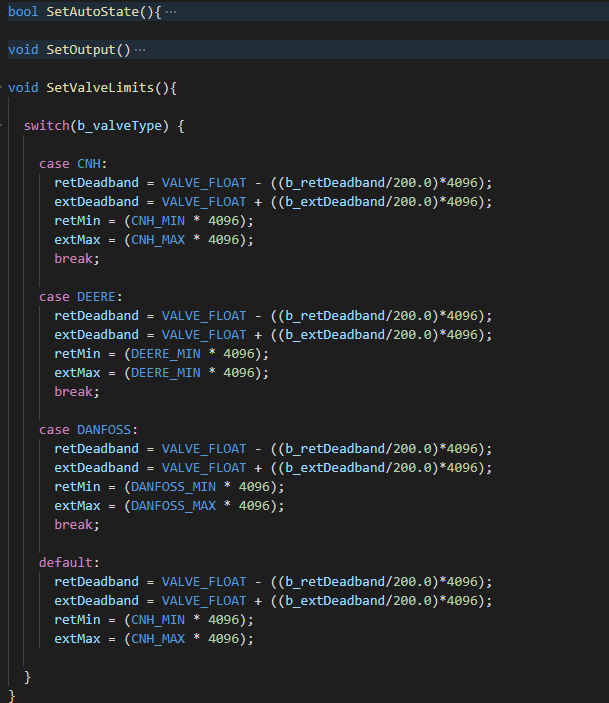
Yes you are correct. Sort of. It is actually between 25% and 75%. As you can see in the above document . I just used 12V for simplicity. CNH and Deere are the same if it get below .5 volts or above 4.5(10%-90%) it creates an error, when you select a valve type from within OGX it sets all Mins and maxes in On the grade control module. So it will not create any errors
If it’s canbus, it’s dead easy as Danfoss uses standard isobus codes.
As for PVG, there’s a relief valve in the main module, different versions for closed and open center. The difference is basically a plug, check out PVG service manual. All PVEA series are compatible with one another and use 13 bar pilot pressure, so if you convert a manual-only PVG to electrohydraulic, check that you have the pilot pressure reduction valve in the valve group. PVHC actuator uses a higher pilot pressure, don’t go for that as it’s same price as PVEA and just crappier, no feedback etc. You can also use a canbus actuator like PVEA-CI (which is the same price as analogue ones) and ditch all the Cytrons etc and just use a canbus module on the PCB. For me, this is by far the easiest way to work with PVGs.
All the technical manuals are available on Danfoss website. With PVG32 body you get higher flows and some more exotic options, PVG16 is maybe bit better price point if you’re buying new and still goes up to 80 l/min flow.
5 Likes
I like the idea of the canbus valves, and would like to make a can module in the future. So I will definitely seek your expertise when I get around to tackling that.
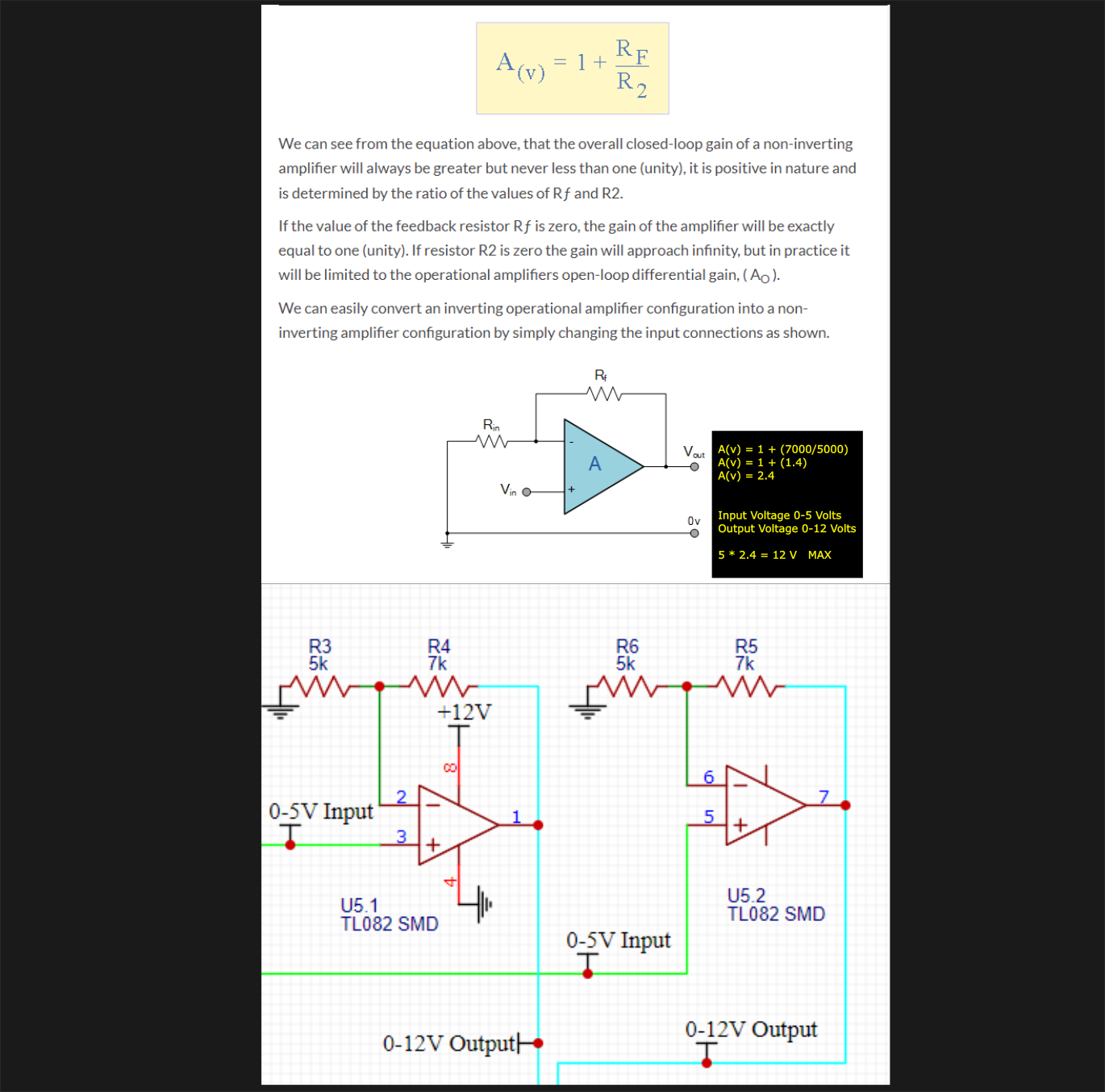
Here is the Op amp circuit that I am looking to use for the Danfoss Analog valves and plan to add to the Grade Control Module. If anyone who knows a little more about the electronics side of things, or knows someone that does would be able to let knew know if this is a viable option it would be greatly appreciated. I understand the premise of it but am curious to know how you select the resistor values. And by this I mean to get a gain of 2.4 you could use a 7k and a 5k, but you could then also use a 8.4K and a 6K resistor. Not sure what difference those values make to the circuit, or if they do at all.
From my understanding OpengradeX is able to tilt the grader/scraper correct?
Will it be able to do that if the implement only tilts on one wheel, with a hydraulic cylinder controling the entire rear end and one cylinder placed on one wheel making it able to tilt?
Would really like to get started on this project since it would be great for leveling out fields and filling up low spots that look flat to the naked eye
The ability to control two SCV’s is readily available to modify in code to however you would like. I don’t think I will spend much time for second scv control in the near future as it isn’t pertinent to my uses for it this year. But the v2 PCB’s that should be showing up shortly have dual DAC’s as well so it’s all there waiting to go.
As well 3D style control that would demand is better suited for OpenGrade3D, which has been developed by some very smart guys it can be found at Grade control
Also I figured out the op amp thing so the V2 grade control Modules also have implemented support for 2 Danfoss PVEM style valves as well.
1 Like
Few Updates
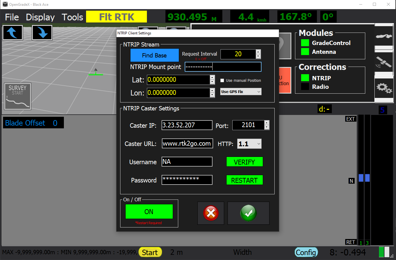
- Added Wireless NTRIP Correction to Antenna Module
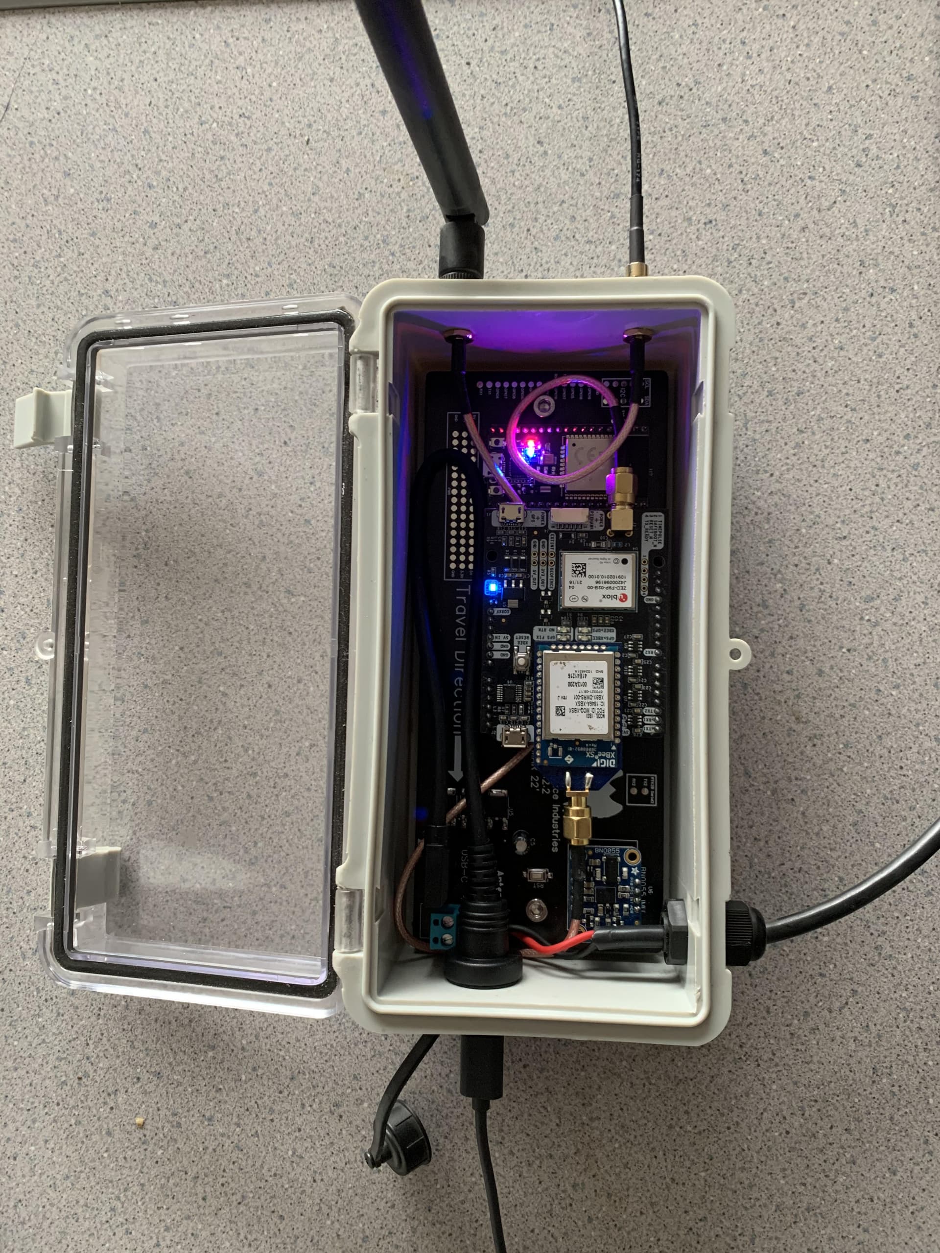
- V2 boards came in, have been built and tested everything so far seems to be working well.
- The system is now 100% wireless just run 7-12V power to antenna module connect to the OpenGradeX WiFi network and go.
- Grade control module sources power from tractor and auto connects upon powering up, as well as reconnects if the connection is lost at any point during operation.
- Can receive Correction from both NTRIP and Radio simultaneously(as long as they are the same stream) to fill in correction data where either system may lack.
- V2 grade control Modules can run Danfoss PVEM Valves
5 Likes
Great work. Looks like I’m going to have to build me one of these!!!
1 Like
Hi, I’m new here… I’m from a small farm in southwestern Ontario. We use a pull behind dozer blade for leveling out old fence rows etc and I would like to add some kind of grade control to it, I have read through the old forum and this one and what you guys are working on is awesome. I’m a little fuzzy on what type of receiver for gps you are using? Can I run NMEA data from an rtk enabled receiver such as an Emlid RS2 or a JD Starfire 6000 (with appropriate harness to get the nmea data out of it) I currently use a program called fieldgenius from microsurvey in B.C. And it works well but it is just machine guidance and surveying, I still have to watch the screen and run the machine myself. I like the idea of tapping into the tractor SCV for our 6r and 8r Deere tractors but some of our older equipment does not have electronic SCVs so I would need to know how to use a proportional Valve with this system. From what I understand the program just runs on a windows machine?
If someone has any insight to my inquiries that would be awesome, thanks
2 Likes
The boards utalize the RTK2B board for GNSS data, but I’m sure NMEA serial data from any receiver would likely work as long as you get the right logic level and messages sent. As for machine control the grade control module can run a 0-5 signal (Deere and CNH SCV) or a 12 v signal for a Danfoss PVEM external proportional valve. It runs on windows
1 Like