Edit: Title changed from: “Panda: using Reach M+ instead of simpleRTK2B?”. Since making the post I switched to an AIO PCB V2.5 standard version (not micro) instead of the originally planned Panda setup. Solution details link.
Is it possible to use an Emlid Reach M+ instead of a simpleRTK2B in a Panda build? If it is, than how can I do that?
I’m in the planning phase of building an autosteer system and I’m considering the use of the Panda board for increased single antenna accuracy. I’d like to ask for some help with the abovementioned question.
I already have a working guidance system consisting of the following parts:
Panasonic ToughPad FZ-G1 – Windows 10 tablet with AOG
2x Reach M+ RTK GNSS receiver with Tallysman TW4721 antennas – one as base and the other as a rover, which gets the correction data from the base through the internet.
I want to integrate the rover M+ into the Panda board, if that’s possible.
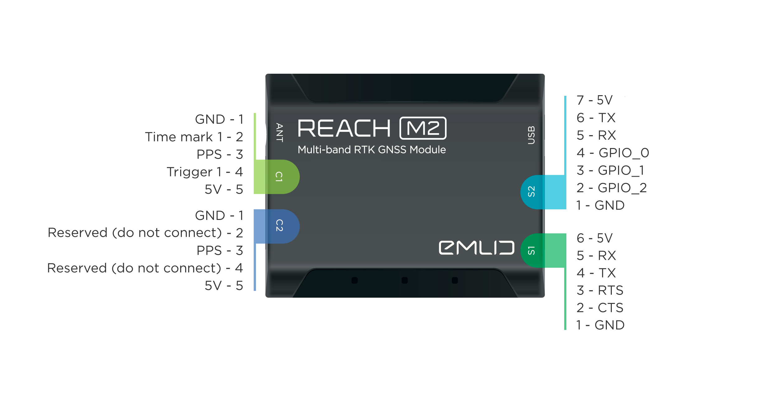
Connectors pinout (it’s an M2, but it should be the same as an M+): Link
The M+ can output the position data (which can be RTK corrected or not) in multiple ways:
Serial: UART, USB-TO-PC, USB-OTG
Baud rate: 9600, 19200, 38400, 57600, 115200
Format: LLH, XYZ, ENU, NMEA, ERB
TCP
Format: LLH, XYZ, ENU, NMEA, ERB
BT
Format: LLH, XYZ, ENU, NMEA, ERB
Additional settings for NMEA format:
Talker ID: GN, GP
Message type (all of them can be selected at the same time): GGA, GSA, GST, GSV, RMC, VTG, ZDA; output rate can be set individually for each message type: 0.1 Hz, 0.5 Hz, 1 Hz, 5 Hz
Yes send gga out the S1 port at the data rate specified in the Panda .ino directly to rx/tx to the teensy uart for gps1. Emlid ttl is 3v, but power supply is 5v.
Or optionally use a ttl to ethernet adapter on the S1 port like the EPort 20, and use my Panda .ino and setup file for the eport. But change the baud to 115200.
Thank you for your response @PotatoFarmer!
I’m new to these things, but I tried to understand your answer. Can you please confirm that my understanding is correct?
Is that correct?
What does “gps1” mean?
Also, I don’t understand what am I supposed to do about the TTL of the M+ being 3V and the power supply 5V? Are we talking about the power supply of the M+ or the autosteer/Panda board(which includes the Teensy), since both of them are 5V?
The inputs and outputs of the teensy / m+ are 3V, if for some reason they get 5v they will pop.
But the main supply voltages are 5v do not mix.
I have to double check the aog pins but you do have the right idea. Tx/rx will be connected to whatever ends up working, may be tx to tx instead of rx to tx. Its 50/50 for rx/tx.
You will also need to attach the m+ s1 ground to the teensy ground
Gps1 is single gps, the teensy can also use dual gps.
I used to use m+/m2 for all experimemts. Now use m2 for base and breakout boards for rovers. I really like the M2 for base.
What do you mean by that? If you don’t understand my pin notations, then you can take a look at the resources(2, 3) I linked in my previous post, it should make things clear for you.
And what about the correction data from the base, should it be sent to AOG directly or to the rover M+, which in turn outputs the current RTK corrected position (correction data from base + its own position data) to the Teensy?
Just replying on cell phone so I do not have the schematics available for pinout. But sounds like you have done the research.
The gps data will constantly stream out of the tx line on s1 on the m+, the corrections will come out of the teensy into S1 on the m+. Uarts rx/tx are independent, thats why the ground connection is required.
Emlid will give you extreme flexibility for correction connections. But I find its easiest on the rover side to just use agio, then you only have to get internet to the tablet to start using the gps.
I got it, thanks for your help!
I’m going to report back about how things will be going when the time comes for the assembly (hopefully in one month or maybe in a few more), for future reference, for those who may be interested.
So I’m back at it and I have the hardware, but now I have the standard version (not the micro) AIO PCB V2 instead of the originally planned Panda setup.
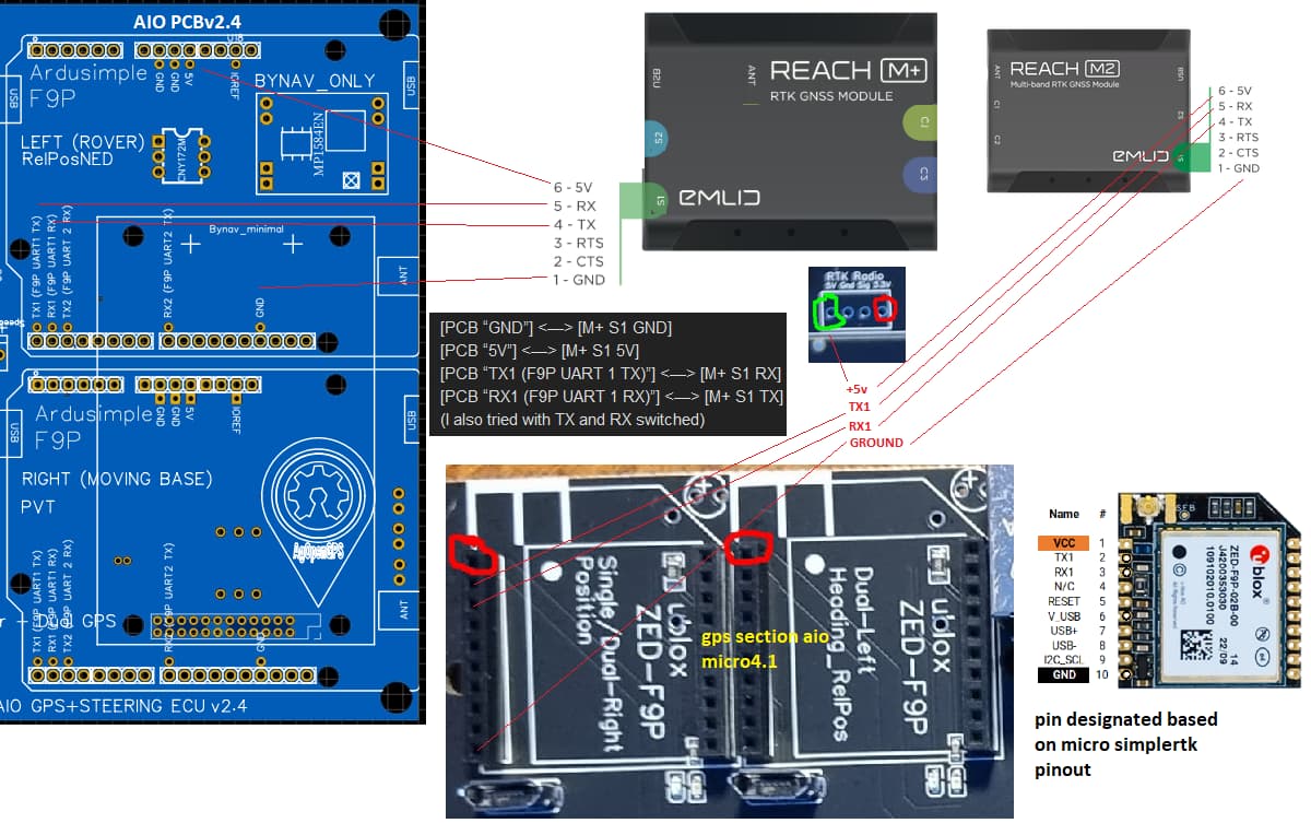
The board is assembled for bench testing and it looks like everything is working except for the GPS (even the M+ used as base is working, it is sending RTK corrections to AOG). Instead of a sRTK2B F9P I have the M+ connected to the board’s “RIGHT (MOVING BASE) / SINGLE” section like this:
[PCB “GND”] <—> [M+ S1 GND]
[PCB “5V”] <—> [M+ S1 5V]
[PCB “TX1 (F9P UART 1 TX)”] <—> [M+ S1 RX]
[PCB “RX1 (F9P UART 1 RX)”] <—> [M+ S1 TX]
(I also tried with TX and RX switched)
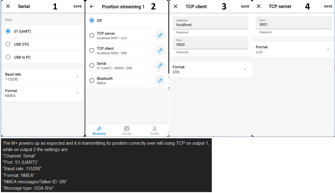
The M+ powers up as expected and it is transmitting its position correctly over wifi using TCP on output 1, while on output 2 the settings are:
“Channel: Serial”
“Port: S1 (UART)”
“Baud rate: 115200”
“Format: NMEA”
“NMEA messages/Talker ID: GN”
“Message type: GGA 5Hz”
The baud rate in the .ino for the Teensy on the AIO PCB V2 is 460800 and I can’t set the M+ to that value since 115200 is the biggest available.
In AOG and AGIO the GPS looks like its not working/recognised. It says no GPS and in the UDP settings the GPS is red while IMU and steer are both green, but only steer has an IP address next to it. Using simulator mode the WAS and the motor works.
Do you (or anybody else) have any idea how to make it work? Thanks!
M+ all you have to work with so your speed is what it is. Ideally faster is better as long as there are no errors. The faster the data is received the faster you can use it.
I’ve changed the value of the “baudGPS” variable, now it looks like its working, only the GPS led is red (previously it was unlit) but its supposed to be green while RTK is active. AOG says RTK is working. NTRIP is set up in AGIO and AOG is receiving the corrections then sending them to the M+ through the PCB.
Also since the M+ got detected and working the led on the Teensy (next to the white button on the top of it) started blinking in orange.
What could be the problem?
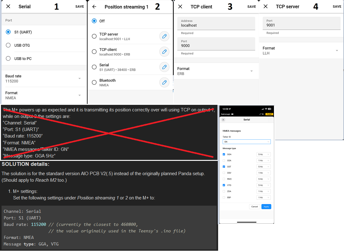
The solution is for the standard version AIO PCB V2(.5) instead of the originally planned Panda setup.
(Should apply to Reach M2 too.)
M+ settings:
Set the following settings under Position streaming 1 or 2 on the M+ to:
Channel: Serial
Port: S1 (UART)
Baud rate: 115200 // (currently the closest to 460800,
                  // the value originally used in the Teensy's .ino file)
Format: NMEA
Message type: GGA, VTG
Changing the value of the baudGPS variable:
Follow the instructions on Configuring the Teensy from the official hardware wiki until you reach the part where you supposed to compile the code and send it to the Teensy then do the following:
Search for the the variable (CTRL+F), currently it’s on line 38.
Change from:
const int32_t baudGPS = 460800;
to the baud rate set on the M+, 115200 in this case:
const int32_t baudGPS = 115200;
then continue with the instructions.
Wiring
Use the JST-GH 6-pin to jumper pin cable (looks something like this) included with the M+ plug it in the S1 port then connect the wires in your preferred way (easiest way is to plug a pin in to the ends of the relevant cables then connect them to the header on the PCB) to the board’s RIGHT (MOVING BASE) / SINGLE section like this (connectors pinout):
[M+ S1 GND] <—> [PCB “GND”]
[M+ S1  5V] <—> [PCB “5V”]
[M+ S1  TX] <—> [PCB “TX1 (F9P UART 1 TX)”]
[M+ S1  RX] <—> [PCB “RX1 (F9P UART 1 RX)”]
(only works one way TX-TX/RX-RX not TX-RX/RX-TX)
That’s it.
Notes:
For some reason the GPS/RTK led on the board stays red which should mean there’s no RTK, but I have RTK anyways.
I had concerns about the baud rate is going to be too slow at 115200 for autosteer, but after a few days working at 8 km/h it looks like it’s working fine.
Edit: I forgot to thank @PotatoFarmer once again for his help: thank you!
Hi Lloyd and all! I am trying to do what you did using m2 as GNSS (vs your M+) as component of a micro aio v4.1 board (vs your aio2.4). I wired it as shown in the image below mimicking what you did with your board. The result no gps coordinate showed up on AOG AgIO. By the way, I changed the baudrate from the 460800 to 115200 before compiling and uploading in arduino. Also changed the output on emlid to 115200 on serial. Any advice is very much welcome. Thx.
Hi! Thanks for the reply. I assume my physical wiring is correct. Below are the screenshots in emlid flow (emlid 3 is gone!).
Can you help what I need to do relative to “position 1 using TCP on output 1”. There are two options TCP server and client. I assume I will select server [4]? The sub-menu when selecting either shows the requirements. No skill in network setup and instructions on which to choose [3 or 4] and what info to put in will be appreciated.
Regarding serial on position 2, I can choose S1(UART), Baud rate and format. I am not seeing NMEA messages/TakerID: “GN” and Message type: GGA 5hz. Are these attributes found in other menus within emlid flow? Can you point me on how I go where to set those values.
Judging by the screenshots from the post it looks like you’re using my older post as reference instead of the step-by-step “solution details post”, try reading that.
Position streaming 1 or 2 need to be set to serial S1, the other one doesn’t matter.
Keep in mind that I’m using internet to receive the corrections, while you’re using radio, but both of them have to be set up just like in a normal setup.
Thanks. I’ve updated the old reference with the relevant step by step section. Still my question is how do you set message to be GGA, VTG. Which part of emlid flow do I set those? For some reason, I am not seeing the NMEA settings (see screenshot lower right) which should be part of the dialog screen once format is set to NMEA from the default ERB. In addition to asking the question here, I am also asking in the emlid community forum similar question.
You can try to use the web interface to set the message types. Enter the IP of the Reach in a browser’s address bar to open the interface. The Emlid app tells you the IP address.