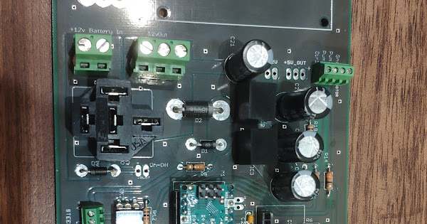
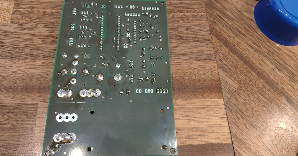
About pcb V2. About soldering and getting it to work
Anybody got a picture of a soldered PCB? I’ve finally collected the parts and am ready to solder, but a little guidance would be appreciated…
There seems to be a ‘schematic’ picture amongst the Arduino code that might help a bit. Schematic.png
I have a question about the R8 resistor. In partslist.txt it says it should be 0 ohm. In partslist.xlsx it isn’t included. What’s the meaning of a 0 ohm resistor? Should I not place any, or just solder a connection where the resistor should be? Or find a 0 ohm resistor at the local electronic store?
Hej Morten, You should just put a wire, and that way feed the 3 com ports with + 12 V
I think you wrong with R8. I think it should be a wire.
I am currently assembling the PCB v2 and have also ran into this R8 - 0. Can anyone verify that it is in fact just a wire?
Yes. You can use wire.
I will start building PCB V2.
Is all up to date on here : https://github.com/farmerbriantee/AgOpenGPS/tree/master/PCB/AutoSteerPCB_Gerber ?
thanks
I have been searching through all the threads and see bits and pieces of info regarding having PCB’s made. Wondering where Canada/US people are having theirs made. Getting ready to order parts but wondering where the best place to order the board from is.
Thank You
https://jlcpcb.com is where i got mine from. Have ordered from them a few different times. I’m from Saskatchewan and first time I ordered I had them within 10 days with express shipping. I’ve heard talk of pcb version 3 coming so not sure if thats worth waiting for or not.
Thank You wwfarm for the link and info , I thought that same thing too V3 of the PCB and V4 of the app upcoming. Maybe I will just hold off as I am in no rush yet.
I wouldn’t hold off unless your expert at the job. This project is all about learning. The parts are so cheap. Our early systems we fried components, installed stuff backwards. All part of the fun.
I messed up and double ordered. I have built 1 and may use one more. If someone wants a couple pm me. I would rather give them away than let them go to waste.
LOL expert would be a large overstatement. So much to learn but it is exciting.
Thanks
I have managed to build this. Got the MD13S - Cytron 13Amp DC Motor Driver from
https://www.seeedstudio.com/MD13S-Cytron-13Amp-DC-Motor-Driver-p-3014.html

Please let me know if you see something wrong. Its my first PCB ![]()
Will this board be compatible with the new .ino file brian is building?
I got my first PCP assembled but cant fit BNO055 and MMA8451! Where would you put them? on a separate breadboard and then wires? What are the reasons to use a Ethernet connection to the arduino nano, just more stable than the usb?
Special thanks to wilberttalen and darrenjlobb for the two videos on then internet, was super helpful!!
You got another type than in the component list. The mma 8452 has 6 pins.
Only 4 are used: GND, 3,3V , SCL, and SDA. You wire your 8451 to them, they are NOT in the same order on the two boards.
BNO055, should not be mounted close to any wires with high Amps. max length of I2C (SDA SCL) wire should not be over 10 cm eighter.
I would suggest an alternative IMU for heading if you need heading. Eg. IMU Brick v2
What is the best way to hook up a pressure transducer sensor to the PCB v2? I plan to use that vs a rotary encoder to kill autosteer.
Will this board be compatible with the new .INO file brian is making?
What is a remote switch?

