Hi everyone! My first post on here, so apologies if I’ve asked dumb questions. Wiring isn’t my strong suit and wasn’t sure if my issue required a new topic.
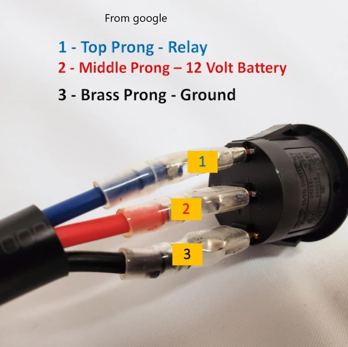
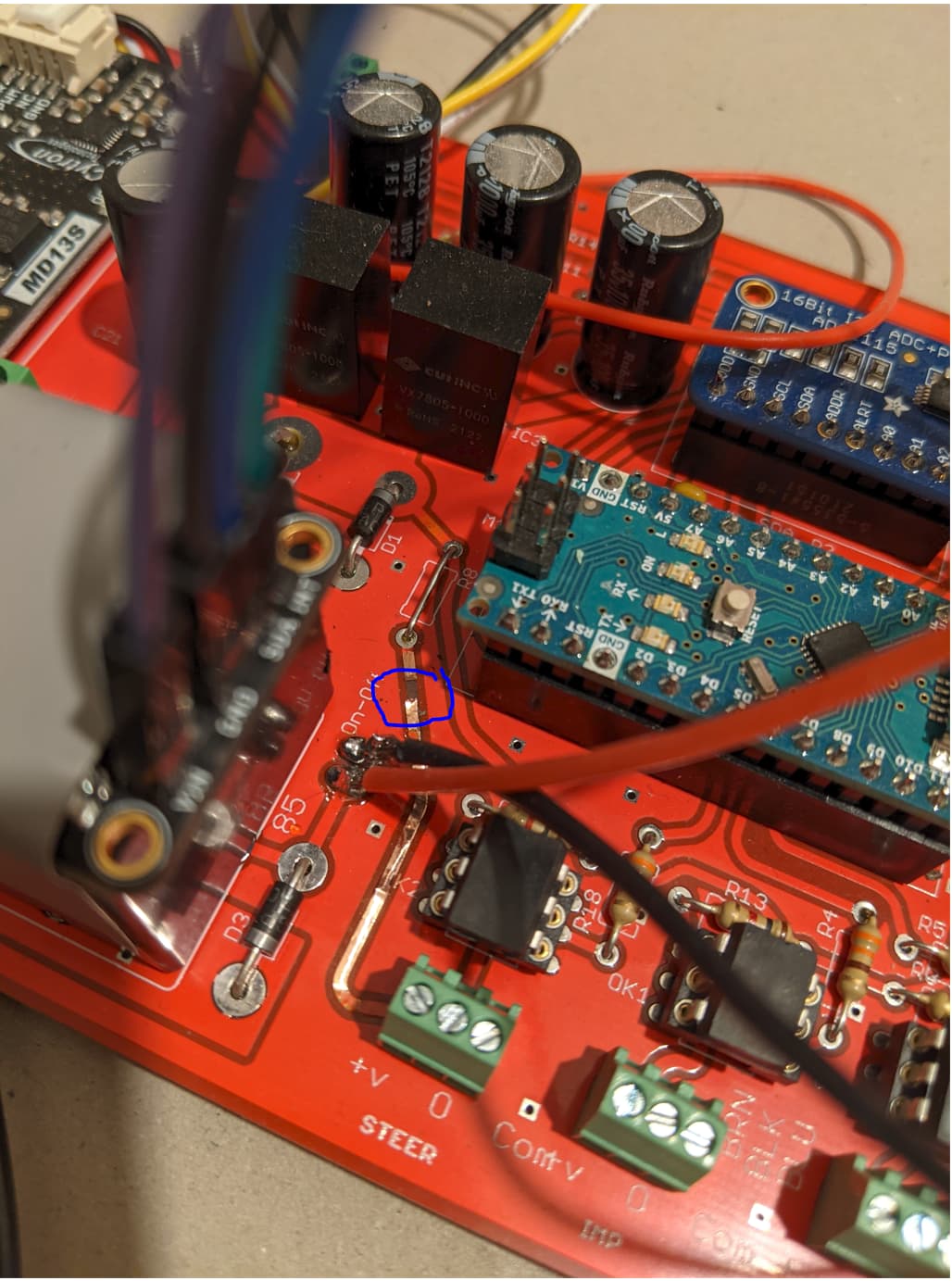
Been working on this project for the last couple months and have made some progress. Successfully put together PCB V2, got readings from the WAS and BNO085, and got the motor spinning using the test buttons on the Cytron. However, I ran into some trouble when wiring in the steer switch. I’m using a 3 pin LED switch shown in the picture, with the wiring pin3 to 0, pin1 to common, pin2 to V+. Not sure exactly what happened, but when I turned on the circuit, there were sparks and smoke coming from the line connecting the steer switch to the 0 ohm (wire) resistor. See the picture of the board, burnt away the coating on top of the strip, and has split it near the wire resistor.
So my questions are:
– Can these 3 pin switches be used, what would the correct wiring be? Read posts about the proximity switch wiring, but these haven’t quite answered my query. Could a quick fix be to reconnect the 0 ohm resistor to the V+ pin of the steer switch somehow?
– How can I test the switch? Can’t seem to work this out in V5, not like in V4 where you see 5 or 7 when switching it, should you see a change in AgDiag somewhere? Can the steer and work switches be tested with the simulator on?
Can always restart on a new board if needed, unsolder or rebuy key parts etc. But would obviously like to salvage this if possible.
Finally, I would just like to quickly thank @pj_05 for his article in Farmers Weekly which originally introduced me to AOG, of course Brian and the development team, and everyone else on here! For my family’s small UK farm, gaining access to autosteer systems with RTK level accuracy has never been an option, until now!! Thanks, Rhod
Yep I have been using that schematic, but didn’t realize the 3pin switch would be any different to the 2pin. I’ll order some standard on-off switches
Once the switch it connected though, do you need to do anything else to make them function? Not exactly sure of what the ‘Enable Work Switch’ and ‘Enable Steer Switch’ settings do. Will they work in the Sim or does GPS module have to be connected as well?
And yes, didn’t think that was the best placement for BNO, I’ll reposition for the final install
Hope your pcb still light up when you supply 12 v to it, but the only thing that you can ruin by the short you just made (between V+ and common) is the big diode D2.
You can use your switch but only connect pin2 to O, and pin1 to common /gnd.
Your switch can not make the led inside light up using it this way. That requires 12v at pin2 and the led can light because it has gnd at pin3 (only reason there is a pin3) The led would normally light up when switch is on, and 12V is coming out of pin1.
You can test in Sim using drive mode.
Thanks for the advice, have wired up the steer and work switches. Yep, the PCB still lights up and everything seems to be working, apart from the switches.
I’ve tried using drive mode, but get nothing. The steer switch needs to be on for drive mode to work, so implies that the switch is not working correctly? Not sure what else to try…
You must have the correct settings in AOG to make switch work. You do not need to have a switch if you set it up for that.
If you search for steer switch, this is one of the hits : Enable Steer Switch
Yep been through all the settings that I know of: ticked ‘Enable steer switch’, made sure switch is set as switch, saved and sent it, and have the steer option set to remote.
Waiting for a USB hub to arrive this week, can then try with both PCB and GPS plugged in
Make sure your switch is connected between Signal (Center pin) & GND (Right Pin).
The arrow in bottom right corner should be Red, or Yellow, or Green. If its Purple AgOpen is not connected to Nano/PCB and you will have to fix that first.
If your using the latest version 5.4.5 you have to select “Button” for your on/off switch to work. Note: In all other versions before 5.4.5 this was called “Switch”.
‘Enable steer switch’ & ‘Enable work switch’ are in the implement setup pages and are only for the work switch (painting the worked ground etc) nothing to do with the steer switch.
‘Enable work switch’ only paints line if the workswitch is acitvated.
‘Enable steer switch’ over rides workswitch and paints line if the auto steering is active.
Ah okay, thanks for clearing that up about the enable settings.
I know this has been discussed in other topics, but just to make sure I understand (read through the wiki again): the on/off steer switch will only cut the current to the motor, it will not actually turn on guidance, this first has to be activated in the GUI. Or has this changed in V5?
The steer and work switches are now wired correctly, and apart from the obvious short seen in my original post, the board and soldering seems good. Getting good communication from the WAS and BNO, but the arrow indicator is RED. My steering is connected but not enabled.
Still running on V5.2 as this was my first install, but will update soon
Well again, don’t exactly know what I did but everything is working now!
Touched up one bit of soldering, put in new on/off switches, clicked the steer switch in drive mode, and the motor started turning! Work switch good as well
So probably wouldn’t have needed a whole topic if I’d persevered, but still learnt a few handy things, so thanks all
Just need to sort out the tractor and base station now, exciting times!
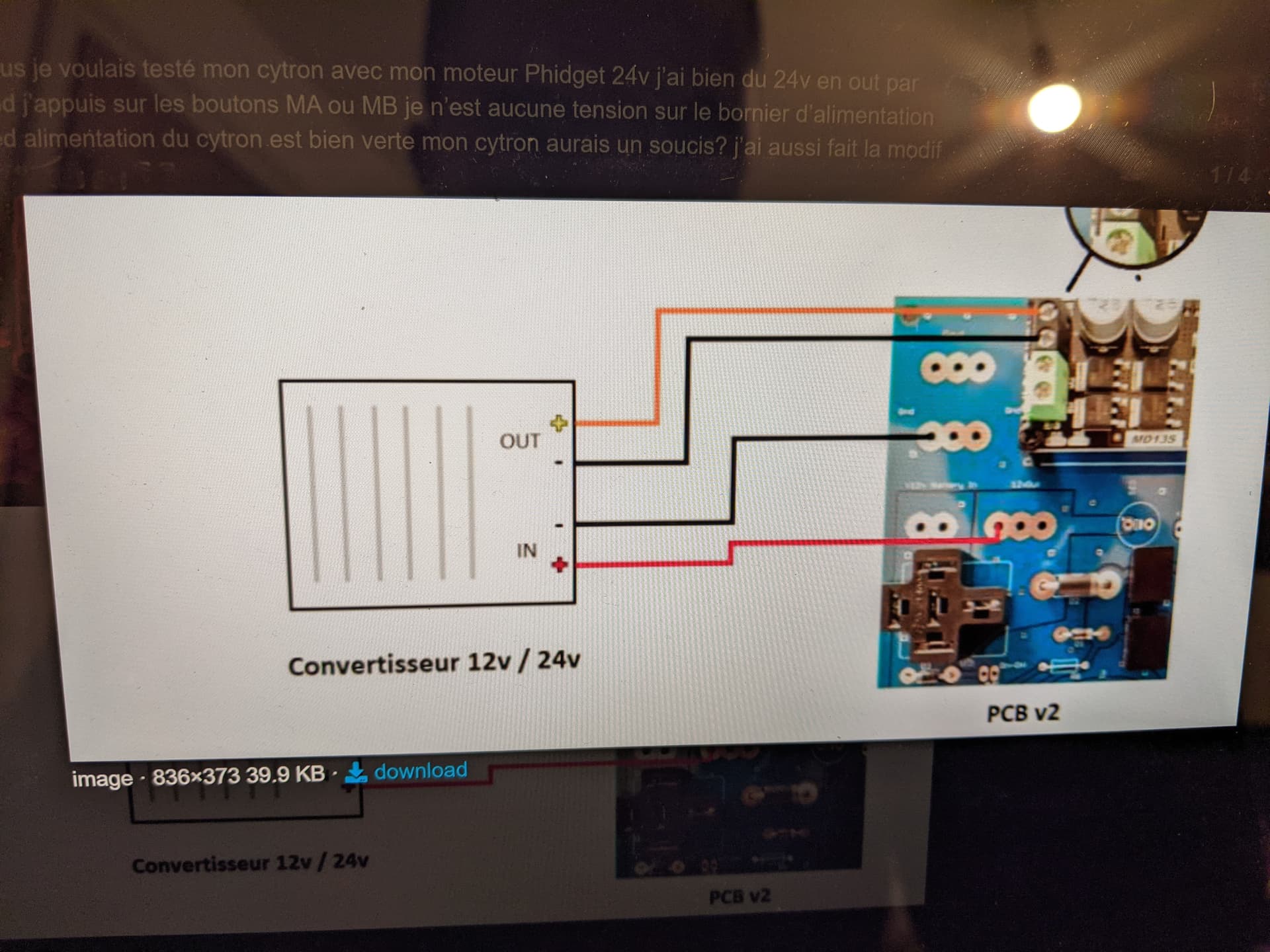
I am having trouble wiring the 12v to 24v converter to the cytron was wondering if the schematic are the same as Kaupoli for version 2 Pcb do all the grounds need to go to a common ground or the 24 v (ground) to the ground on the cytron (as shown on schematic)
Had the same question myself.This is the schematic I used, and worked fine. Sorry took that picture on my phone, can’t remember where the original post is.
Why might my momentary steer switch not be doing anything? Wired up as per schematic, set as button on AOG and settings sent to module. But steer icon remains stubbornly on red.