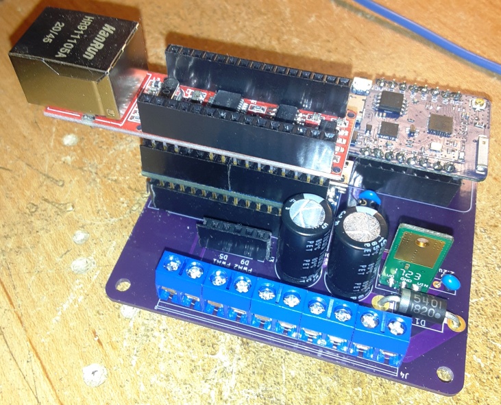
I should have mentioned this sooner, with the ethernet shield pin D2 is pulled high and prevents the Nano from reading it. To get pin D2 to work mount the shield on top of a nano with stacking headers. Make sure to cut off the D2 pin on the shield. This will allow the nano to read D2 without interference from the shield.
Awesome! I made this change but somehow during my handling of the board I have damaged something. I’m testing 5V @ the pins but after a few minutes the nano heats up and burns out. What should I check?
I decided to go with using rte2 instead so I moved the dir and PWM wires on the board. During testing of the board it did intermittently test at 12v instead of 5V. In addition the voltage regulator is getting hot. I have ordered some more 1723 regulators and will replace when they come in.
I had an extra 5V regulator left from putting together a v4 board. I somehow burned out the 1723 regulator that was with the original board. However I now have a few of the MEZD71202A-G that the design calls for.
I decided to restart from scratch with your RC12 board, do I still need to be concerned about the following? I see in the GitHub pics that you have your nano stacked on top.
I believe this is a simple PWM hydraulic valve connected to a pump. I made a new board with new parts and a fresh arduino. It connects perfectly
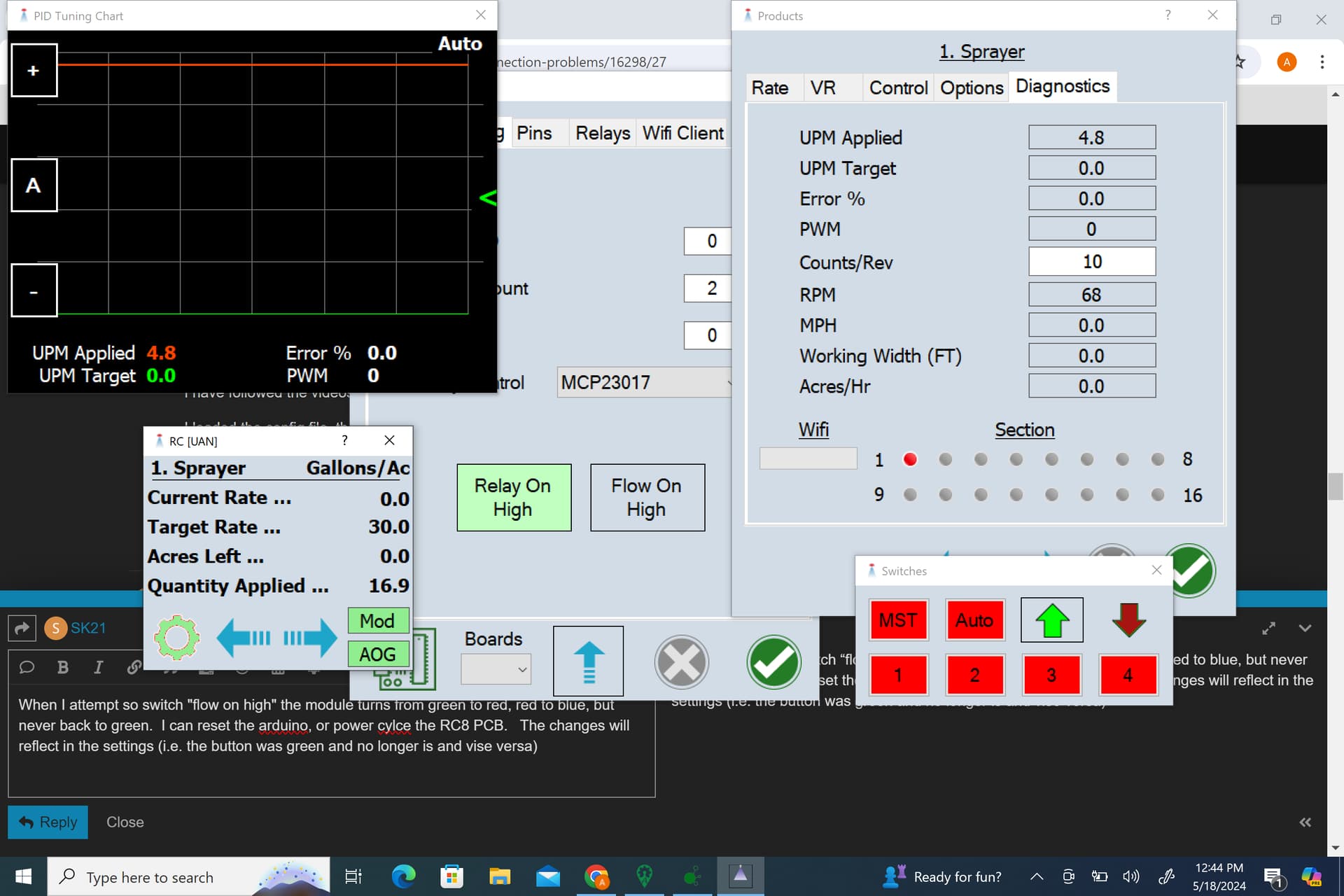
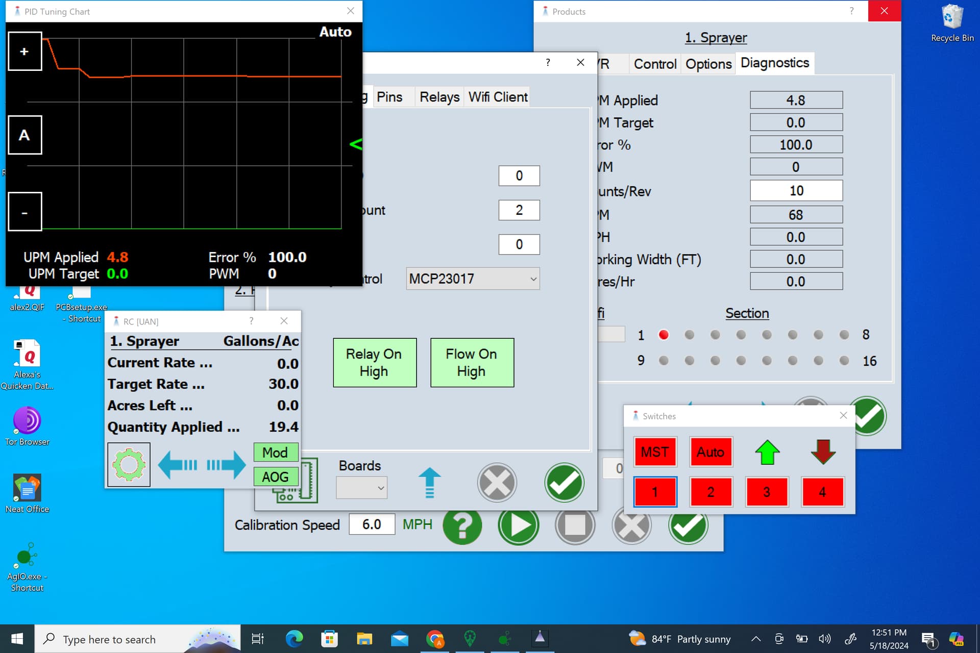
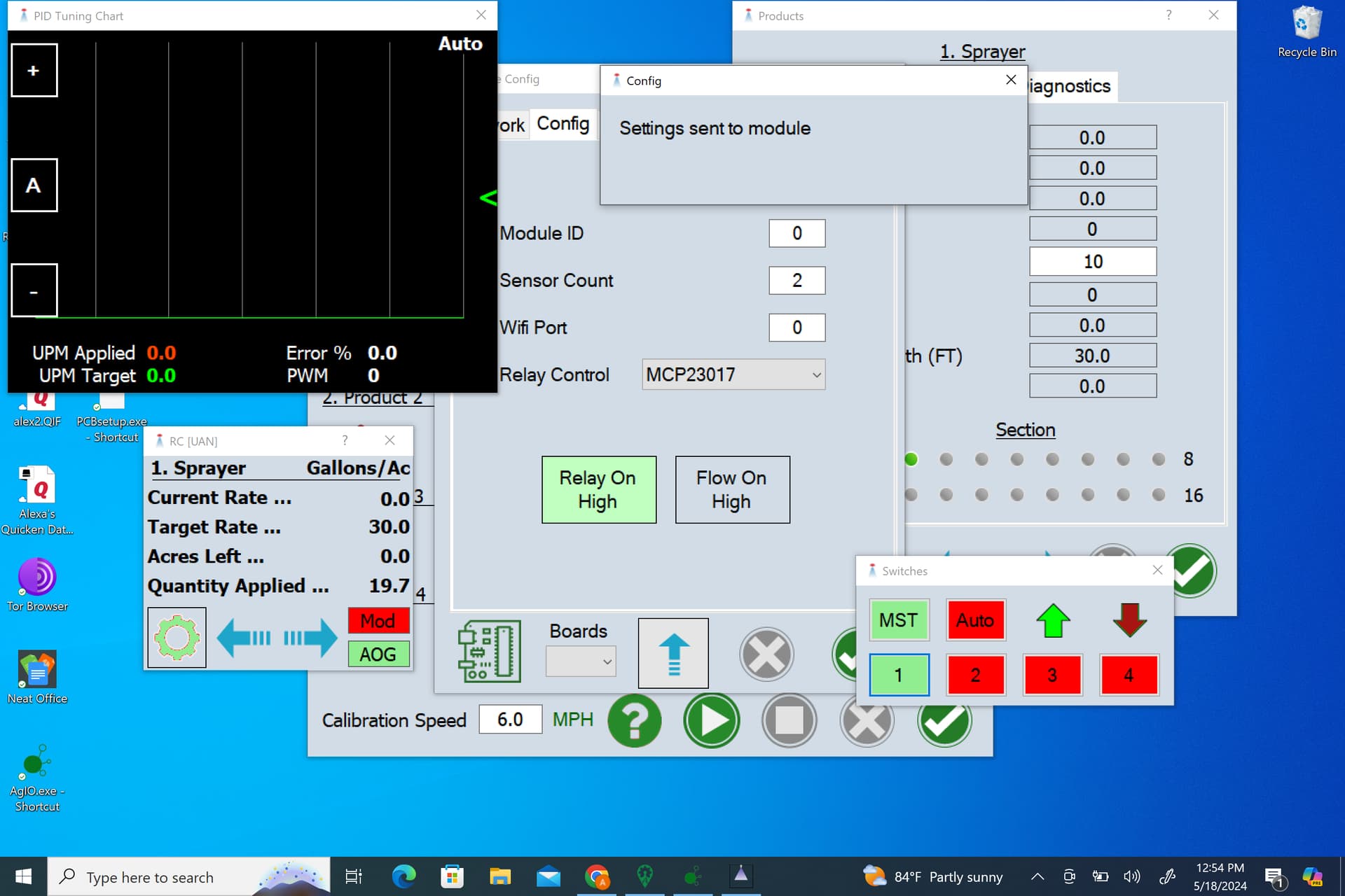
When I attempt so switch “flow on high” , nothing happens. I am running as a combo close (the only way the valve will respong.) The changes will reflect in the settings (i.e. the button was green and no longer is and vise versa) but nothing happens. Thc cytron will go from showing the MA light to showing the MB light but no change in behavior.
I switched over to using the D3 pin and my flowmeter is working perfectly, but I cant calibrate because the valve will only open when he master is off.
When I run as a standard valve nothing happens either way. I’m not sure what I am missing.
Your cytron should never show the ma AND mb lights as that would mean it’s trying to do a direction change. It should just show MA when it’s trying to pulse (mb would need The direction pin high to light up)
The PWM valve controlling the oil is normally closed and opens for a split second with each pulse. The more pulses the more it’s open, the more oil flow.
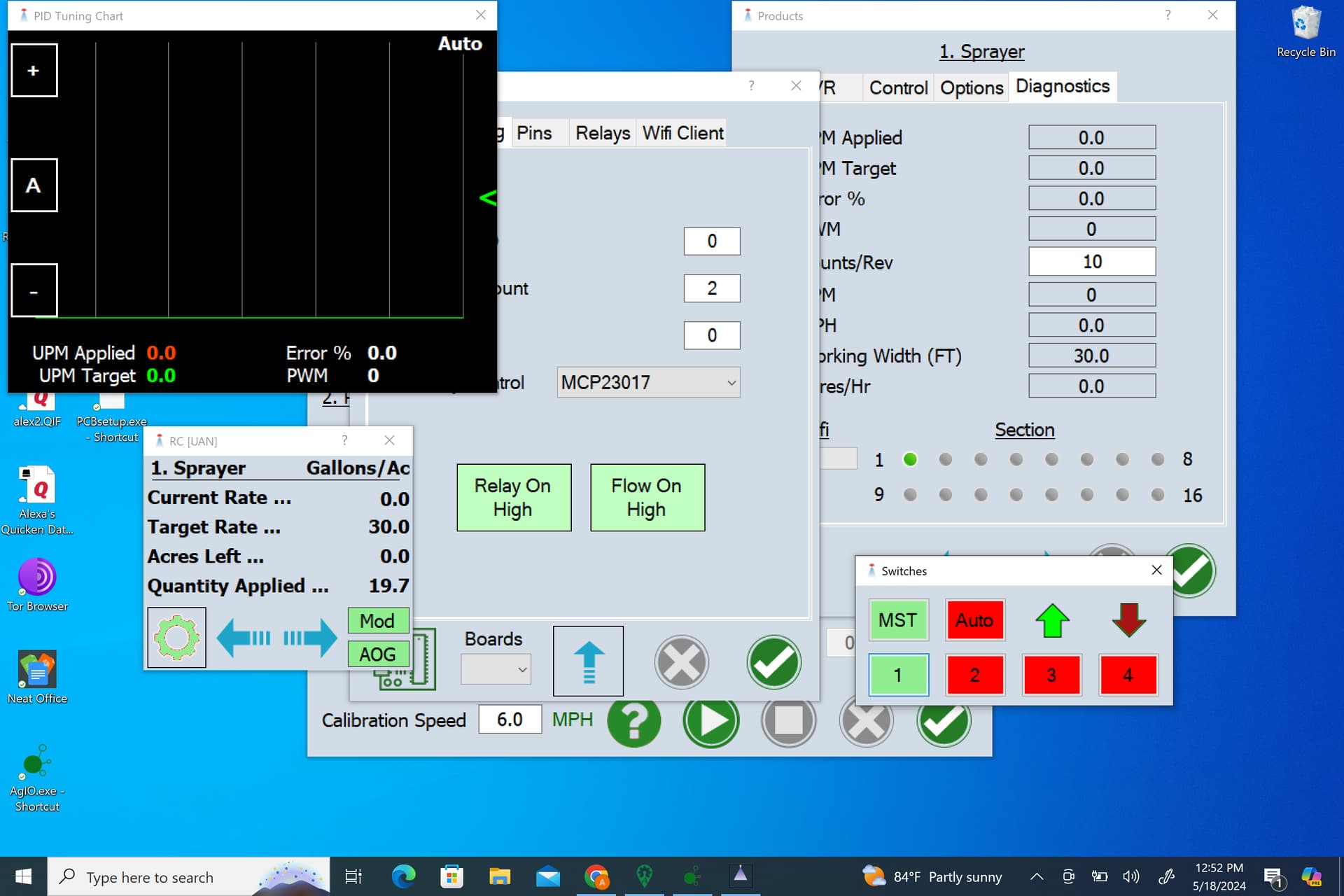
Set it as a motor instead of a valve and see what happens.
The Cytron basically amplifies the input PWM using a chip that can handle the current & voltage needed for valves and motors. So it’s output is still the same duty cycle and frequency as the input PWM.
Not a true analog voltage but your digital multimeter will probably see it as analog. PWM outputs are often called analog outputs but it needs smoothing to be true analog. That’s why your steering motor “sings” while turning, it’s the PWM frequency.
I gotcha, I’ve never seen it showing both, just one or the other.
When I set it to motor it behaves the same as it does when set to standard valves, the valve stays closed. It’s only when it’s set to combo close that I get any oil flow.
In just following this for outside but since you have a solenoid that controls the speed by varying the oil flow it should always just use the same cytron output. If you see MA and MB lighting up then you are not in the right control mode.