Robust dual antenna selection, placment, protection

Planning a dual antenna installation with UM982 (Tri-Band) on a John Deere.
Antennae have to be placed side by side, with a larger distance increasing precision.

Have a lot of trees and low hanging branches along my field edges and ways.

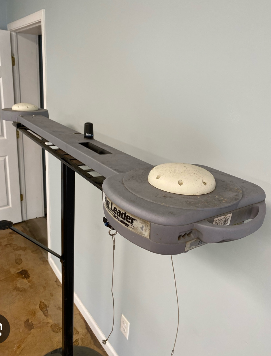
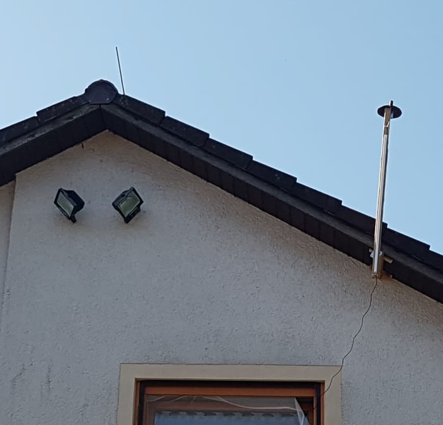
There’s an inspiring example here with survey type antennae

However the author emphasizes that he can manage to stay off low hanging branches. Lucky one.

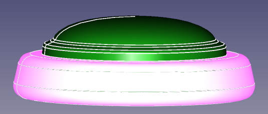
I’d prefer AG-30, they look quite robust (at least in the images, have quite long lead times…) and promise superior signal quality.
But do they withstand branches that fold mirrors?

What are the options to get it more robust?
Some ideas:

  • Go for a flat patch type such as the U-blox ANN-MB2
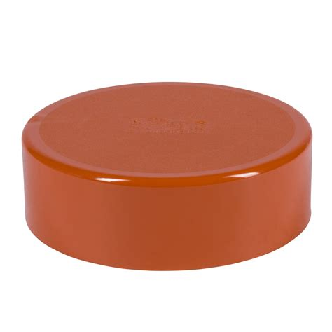
  • add a protective base plate large and stable
    (how large can a base plate be for L1/L2/L5?
    does it hurt performance of a survey type antenna?)
  • add protective bow
  • reduce lateral distance of antennae
  • put a protective cover over the antennae -
    how does it affect receiver performance?
  • put antennae on foldable arms, as used for mirros, e.g.
  • put a predetermined breaking point in the antenna mounting
  • detachable antennae
  • always have some antennae in reserve
  • … ???

Any ideas, experience?

I mentioned I don’t have a lot of tree issues, but my other idea I didn’t use was a local construction supply store sells plastic 2x8 lumber (actual dimensions 1.5"x7.5") I thought of buying one of those plastic board and sawing out a circle the same diameter as the survey antenna. Then I thought I would fabricate a steel strap to screw in the board below the hole that bridged the hole. The antenna would then sit down in the board. The mounting bolt for the antenna would go through the steel strap to support the antenna. In the end you would end up with something that looked like a homemade version of an old Agleader paradyme antenna bar. With the antennas mounted down in the bar with just the domes protruding, it should have good tree branch protection.

https://www.menards.com/main/building-materials/landscaping-materials/landscape-edgers/8-black-plastic-lumber/1129976/p-4221069730084379-c-5783.htm

Yeah, triggers some of my other ideas.
Considered to cover antenna with sewage pipe cups like those


but following your idea, I could as well cut a hole and let the dome protrude.

Will have to make some tests whether thick plastic cover impacts signal

That would be some good protection if it doesn’t affect signal. :+1:

… or we might 3D-print some kind of protective ring

If we assume that

  • the dome is rigid
  • signal reception happens ± above the plane of largest diameter
    so anything below is not causing problems
  • the critical mechanism of damage by branches its to get them caught in the angle below the largest diameter
  • 200 mm can be printed easily

That looks like a nice way to go. That would look neat and clean when installed.

Just ordered 10 of AG-30 or a total of ~ 250 €uro. Lets hope they are up to spec.
Would provide some room to test for rigidity :man_shrugging: :innocent: :axe:

Euhm you doing um982 and buy l1/l2 antenna. May i ask why not triple band?

Sure?

That’s what the specs say:
GPS: L1/L2/L5
BDS:B1/B2/B3
GLONASS:G1/G2/G3
Galileo:El/E5a/E5b/E6

It was this post that raised my attention for the AG-30

The AG-30 Looks like a clone of a Trimble AG-25 (still sold at $1700 or so). Of course I know that cloning a case design does not say much about the interior.

… For instance, when your forestry fieldwork presents the threat of impact from falling trees, this dome protector will cover your entire antenna.

That’s a bold claim, isn’t it?


Actually, I was searching for a test setup for our question here at hand.

From my halfway educated guess, I darkly remember:

  • malformed or malsized groundplates - as any other counductive metal gear - might detoriate RF performance
  • plastic cover introduces dielectric impact, coming with phase shift and RF attenuation

My current “idea towards a plan” is

  • take my base-station-to-be UM980 as reference
  • for concentric distortions (groundplates of different diameters, plastic cover, plastic with cutout, 3D-Ring) connect the seutp-under-test to an UM982 and compare SNR-by-elevation plots to the UM980 reference
  • for ill-shaped (branch bouncing) groundplate shapes and supportive metal structures, I think not only detoriation of SNR, but a shift of phase center might be the problem. So my idea was to use a coordinate plot over a longer time (24 hrs?) in RTK fix related to the close-by UM980 as base.

Any better idea?

No better ideas sounds solid. :+1:

Great ideas, if you don’t mind I’d add a few more.

People often install these antennas on the hood of the tractor. If the cab is very close (15-30cm) I think the signals can bounce in a way that we get only RTK Float. If it’s further 50+ cm then it seems to be much better.
Which leads me to the next question: New harvesters have very tall grain hoppers. Often made full of metal. If we place antenna 1 meter from them how would that affect? For this you just need a big vertical metal plate.

Ardusimple had a test where even 1cm of water on top of the antenna made it see 0 satellites so the water definitely have a huge impact.

Those obvious cases of signal obstruction I’d consider as skd of low hanging fruit.

There is a

u-blox White Paper
Achieving Centimeter Level Performance with Low Cost Antennas

and

u-blox GNSS antennas - Application note

(in particuar section “2.3 Antenna placement”)

dealing with such issues.

Our GNSS wavelength is ~ 20 … 25 cm.
Obstacles that close to the antenna imho might interfere with the near field and spoil the very antenna design.
At a distance of several wavelengts, we’d approach the reign of simple geometric optics. So the corn hopper might be considered in terms of simple shadowing, which should clearly be visible in a sky plot or the “Sky View” aggregation advertised in above app note.

However, the metal hopper is reflective, too, so it will also create severe multipath for satellites in open view line. This may not so obviusly be visible in the CNR figures.

Just unearthed an old script

perl-nmea/plot-CNR-from-GPGSV.pl at master · wolfgangr/perl-nmea · GitHub

building on ideas from Josef Gerstenberg

GNSS-Antennen für Trägerphasenmessungen - Seite 4 - Geospector GPS-Forum (vormals kowoma GPS-Forum)

Gerstenberg plots the standard deviation of CNO/CNR over elevation and finds oscillating patterns as indication of multipath.

Sadly, said script was written in times of L1-GPS-only test data. Rewriting it for todays multi-System-multi-band data with hundreds of megabytes just for an hour of 1Hz-G*GSV data is more than a no-brainer.

But I’m heading for sustained cm-precision, so not only obvious m² sized obstructions far above horizon, but also subtle multipath effects from odd-shaped groundplates, dielectric distortion from plastic covers and conductive antenna mounting frames might play in.

So let’s go and rewrite the thing. :man_shrugging: :muscle:

1 Like

Managed to rewrite my script to cope with multiband setup now.

perl-nmea/plot-CNR-from-GPGSV.pl at 0108 · wolfgangr/perl-nmea · GitHub

To process 24 hrs of data logged by an UM982 with this stationary test setup
(view from the North)

overloads my 16 GB workstation.
Good to have a 128 GB spare one… just to produce output to get drowned .. :thinking:

One of my ideas was to overlay skyplot with the ublox sky-view.
However, nearly 200 tracks overlaid are too many trees hiding the forest:

(both plots are color coded SNR over elevation and azimuth)
Can both images benath each other tell us more?

We might guess some obstruction in East-north-east, but actually there is really free view

In the “Gerstenberg-plot” …

…we may identify some oscillations of CNR stdev between 70 and 90 deg.
However, there is unobstructed view beyond doubt, so we might find remnants of the antenna design. May be we can compare antennas thus?

And we may see oscillations between 10 and 40 deg elevation - where we expect the effects from obstructions close to the horizon.

In the hundereds of different per-sat/system/signal views, similiar patterns display clear distinctions, but it’s hard to find relevant information.
Would be nice at least to separate this information by azimuth, to get a clue where distortion comes from.

I tried to recall my old ideas of a “reverse hologram” still present at github. The idea was to map all those CNR-patterns into space to identify sources of reflections. But the numerical challenge of such an endeavour is immense.

Looks like I siply have to collect some experiments and see if there is something to see. :man_shrugging:

Anybody any idea / knowledge how a “perfect” groundplane for an AG-30 and how a “not-so-perfect” one look like?

1 Like