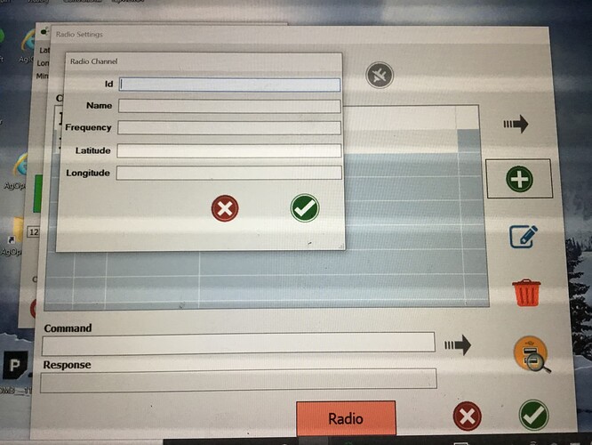
Hi guys I need some help setting up a base station I bought 2 of the XBee-PRO 900HP S3B. Has anyone set up a base station with these modules before and can help or guide me through the steps of setting it all up? Thanks
Are you using the ArduSimple SimpleRTK boards?
Yes 2 of the simpleRTK2B Lite boards
Okay, looks like the radio module just just plug into the SimpleRTK2B lite board. Do you have U-Center downloaded and installed on a computer? Also when you plug the Lite board into your computer via the USB plug, did it ask for drivers? A basic summary of the drivers and getting U-Center installed can be found here: Getting Started with U-Center for u-blox - SparkFun Learn
Sorry for the delay. Tomorrow I’m going to add details of the configuration of the base station in U-Center. Or I’ll link to an existing post because I know this has been talked about before. Searching forums is always difficult.
Yes I have Ucentre and I tried configuring the xbee module with XCTU with my laptop instead of the toughpad that AOG is on. I have no idea on all the settings between the 2 modules. I tried following a youtube video but it doesnt seem to have worked.
This is what I did to get my ntrip master going. I assume should be the same.
On the top bar press view,
Then messages view
Scroll down to UBX
THEN CFG
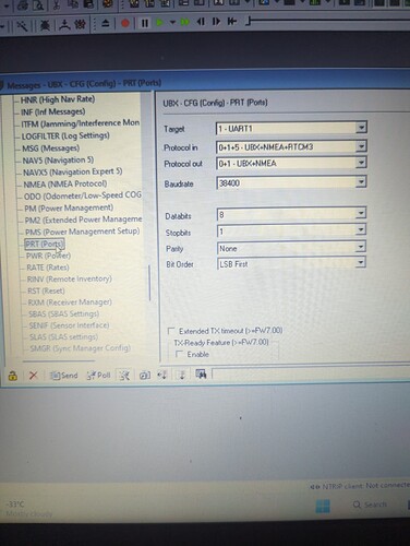
THEN PRT(PORTS)
SET UP LIKE THIS
Need to save each of these with send at the bottom
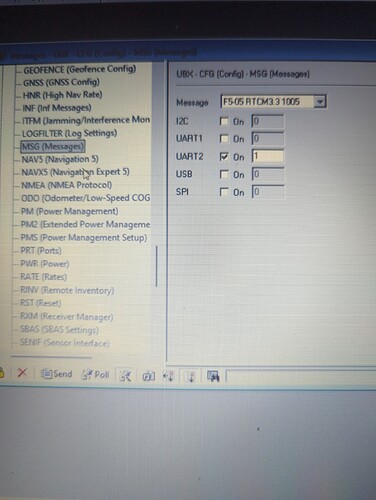
Then from ports click on MSG(messages)
Here configure all the messages you want sent under uart 2
I entered 1005,1074,1084,1094,1230
You may want more but these are what ardusimple said to do on their tutorial
Remember to save everything you enter by hitting send
Just saw this. Watch the video. This guy shows in detail how to set up your base. The ucenter configuration is the last half of video
Here’s how I configured my base station ZED-F9P. There are no doubt other variations people use. I’ll look up your radios and see what they need a bit later.
- launch U-Center and connecting to the ZED-F9P, select “View->Configuration View”
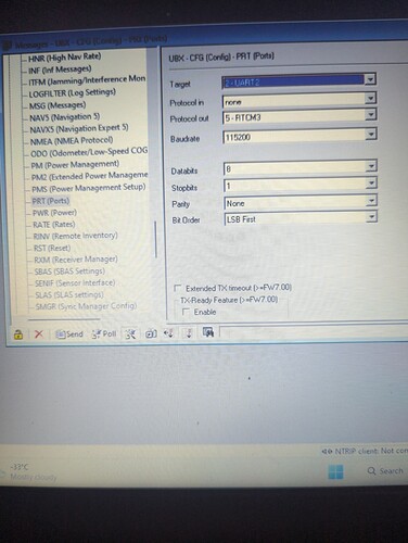
- select PRT (Ports)
- Select Target UART2
- Make sure Protocol out is “5 - RTCM3”
- Set baudrate to 115200 (the default for your radio modules)
- Click “Send” button
- select MSG (Messages)
- For each of the following message types, select them in the “Message” drop down box, then make sure UART2 is checked, and put the number listed in the input box next to the check box, which specifies how often to send the message. Note that for other kinds of roving receivers there might be a different set used. But for ZED-F9P rovers, MSM7 works nicely and you have enough bandwidth on those radios for all of this. Other radios (including Lora) might need a reduced message set
- “F5-05 RTCM3.3 1005” 10
- “F5-05 RTCM3.3 1077” 1 — GPS observations
- “F5-05 RTCM3.3 1087” 1 — Glonass observations
- “F5-05 RTCM3.3 1097” 1 — Galileo observations
- “F5-05 RTCM3.3 1127” 1 — Beidou observations
- “F5-05 RTCM3.3 1230” 10 — Glonass code biases; not sure if this is required for any modern GPS receiver
- click “Send” button
- For each of the following message types, select them in the “Message” drop down box, then make sure UART2 is checked, and put the number listed in the input box next to the check box, which specifies how often to send the message. Note that for other kinds of roving receivers there might be a different set used. But for ZED-F9P rovers, MSM7 works nicely and you have enough bandwidth on those radios for all of this. Other radios (including Lora) might need a reduced message set
- Select “RATE (Rates”
- For each time source in the drop-down box, set measurement period to 1000, set Navigation rate to 1 cyc.
- This will set the base message rate to 1 per second, which is what you want for the RTCMv3 messages coming from the base station
- click “send”
- Select “TMODE3 (Time Mode 3)”
- If you want to do a survey to find the average base station coordinate, select mode “1 - Survey-in”). This can be changed to a fixed location later when the base station is permanently mounted
- Set the minimum observation time to at least 120 seconds
- Set the Required Position Accuracy to 1 metre. You can make this finer but honestly it doesn’t need to be. RTK is all about relative accuracy, not absolute.
- Click “Send” This should start the survey process. See step 7 for how to monitor the process
- If you want to set the base station location (perhaps using Google Earth as a reference), select the mode to be “2 - Fixed Mode”
- check the box that says “Use Lat/Lon/Alt Position” if you have coordinates in that form from Google Earth
- enter the latitude, longitude, and altitude in the fields, or if you’re trying to make a survey-in permanent, enter the ECEF coordinates (see #7 below)
- click “send”
- If you want to do a survey to find the average base station coordinate, select mode “1 - Survey-in”). This can be changed to a fixed location later when the base station is permanently mounted
-
Save settings to flash very important
- Select “CFG (Configuration)”
- Select “Save current configuration” radio button
- Select “0-BBR” and “1-FLASH” under devices (should already be highlighted)
- Click “Send”
- How to monitor survey-in process
- From main menu select “View->Messages View”
- Find “UBX” in the list and double click it.
- Select “NAV (Navigation”), “SVIN (Survey-in)”
- click the “Poll” button to refresh the information.
- when complete “Mean Position Valid” field should say “Yes”
- can use the the ECEF coordinates as a “Fixed Position” in step 5 above to make the base station position permanent.
- Download configuration file in case you need to set up a new base station later
- From the main menu select “Tools->Receiver Configuration”
- Set the file name you want
- Click “Transfer GNSS->File” button
- Can upload a save configuration with the “Transfer File->GNSS” button
Great thankyou
Great Thankyou
I’m not sure what firmware your radios are using, but in XTCU, if you make sure the parameters are the same between the base and rover radio, it should at least communicate. Each configuration in the radio should have a bit of help information with it. There is likely a setting where you can set a unique code that will prevent other nearby radios from colliding with your broadcasts. You’ll want to configure the rover RTK receiver to not transmit any messages at all on the UART2 port. Should be listening for RTCM only.
arduSimple LR config backups.zip (199.2 KB)
Here’s the backups I made of the config from arduSimple for my LR radios. I think the base and rover configs are the same.
Thanks
Thankyou
Cool, thanks. The XML file that’s in the zip describes each config field is and what it does. (XCTU shows this to you normally.) Really there are just two fields you can change if you are worried about other radios interfering in your area. They are “Preamble ID” and “Network ID.” Whatever you choose, they should be the same between your base and rovers.
Preamble isn’t as important as network ID, although if you’re getting data loss and think that it might be from other transmitters in the area stepping on your transmissions, change it. I always change it from the default.
Network ID acts kind of like a “coded squelch” on the old FM radios. It just marks your radio data packets and the rover will throw out any packets that don’t match its Network ID.
There are a lot of settings there, I found it intimidating at first but even arduSimple only changes a couple from Digi’s default. I think you can use the same settings for both base and rovers, but make sure your Serial Baud matches whatever device it’s connecting to, this can be different between base and rover especially as the new All-In-One Teensy Dual PCB’s use 460800 baud between F9Ps, if you want to feed RTCM directly into the Right/Main F9P you need to match that baud with the Xbee radio.
Looking at the zip file, if you open the .xpro files with something like WinRAR, the profile.xml in the one shows only 5 settings, looks like it only saved those that are different from factory default.
Then if you dig deeper in to the radio_fw/XBee_SX folder, XB9X_9007.xml lists the descriptions that Torriem’s talking about, the same as in the XCTU program.
Here’s the latest that I’m using with firmware 900A:
  <setting command="ID">1234</setting>
  <setting command="MT">0</setting>
  <setting command="BR">1</setting>
  <setting command="TO">40</setting>
  <setting command="NI">Rover</setting>
  <setting command="NO">4</setting>
  <setting command="BD">7</setting>
I’ve wondered about also changing DL on the Rovers to eliminate accidentally RF congestion (if the Rover were to broadcast data from it’s serial port) but changing DL to 0x0 just causes the other Xbees to ignore it, it doesn’t stop the transmitting Xbee from sending. The new AiO Micro PCB leaves the Xbee’s serial RX pin unconnected so that it can’t transmit anything back onto the airwaves but if you plug into the standard sized simpleRTK2B directly then you should probably cut or bend pin 3 to the side.
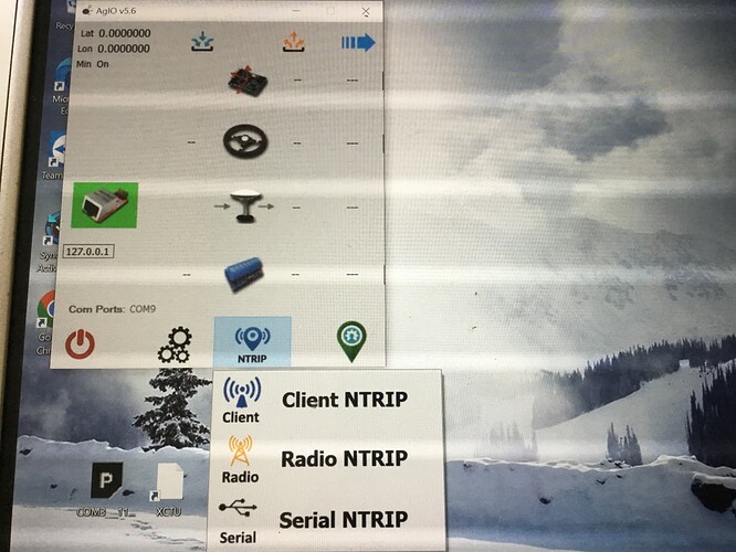
Hi again guys I have configured the xbee’s as you guys described above but Im not sure what I have todo with settings in Agio. Do I have to setup anything in the Ntrip settings even thou Im not using Ntrip?
No not at all. I use lefebure ntrip on phone then bt to xbee.
It’s been a while, what PCB and code are you using?
