Normal, like the answers 10 days ago and one month ago ![]()
![]()
Edit: I was not sure about your pick and place file, but this seems correct.
Normal, like the answers 10 days ago and one month ago ![]()
![]()
Edit: I was not sure about your pick and place file, but this seems correct.
All the files from the same (STD 4.1) Github folder. I only asked because this was not the same error message like the previous ones.
Hello I have used this gerber https://discourse.agopengps.com/uploads/short-url/vE2t4xIiO4hDjh8Y9ZQ1wRW3jpv.zip (post PAT 11th july) and the bom files on Github for the 4.2 std. And all was ok.
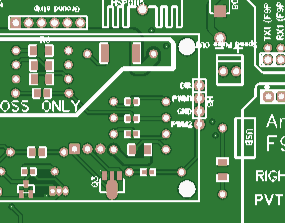
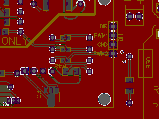
Just a heads up, the V2.5 Std on the Github is not the most upto date it has a fault with the PWM2, this one works:
https://drive.google.com/drive/folders/1UO4FjN2rfQ0w3XsmV4em071r4b1Jbu3s
Why would anyone want the 2.5? Well it has 2x Canbus which you need for CNH tractors for example, if you don’t want to build a Tony CAN PCB.
This shows the fixed PWM2 trace:

The one on Github:

So this is the most updated version?
hello! I’m new to AgO and I’m trying to get used to it, I configured the f9p tenesy boards, now I’ve come to a problem that I don’t understand, namely the power supply of the Cytron and the 12/24v converter, the source has 4 wires, 2 wires 24v and 2 wires 12v which and how do they come into the PCB because I don’t want to burn it and I’d better ask you
If the motor is 12 volt you do not need a 24 volt converter. Connect 12 volts to the input part of the 24 converter. Cytron engine supply (+) 24 volt converter output must be connected. Motor cables should also be connected to the cytron motor output.
excuse me for not being exact, I have a 24v Phidgets motor, that’s why I have the converter, from what I understand pin18 must be powered by 24v and a 7.5A fuse on it? if I’m wrong, correct exactly what I’m doing with - from the 24v converter
Pin 18 is for the 24v converter positive. Think this has a 7.5 amp fuse inside the board. Connect your negative to pin 23 which is earth pin.
If your not wanting to use the headland u turn steering function you can do away without the converter and run the 24v phidgets motor at 12v instead
so that I don’t have problems because of google translate: I feed the converter with 12v from the battery + and - after the output of 24v + that comes out of the converter, I feed pin18 and the output of 24- to pin23 and I connect the motor to pin5 and pin 6, I understood correctly ?
This gives you a list for the pin outs but they do vary slightly depending on what aio board you have so scroll on down the list and you’ll find your aio board
Hello,
I want to upgrade and buy a PCB AIO V4.
I put the BOM and gerber files at JLPCB.
The only problem is that a component SW1_THT is missing, whereas on the 2D drawing in the source file there is a component there.
I’d rather be sure before ordering
Not sure but i see you’ve added the ads1115 module, is this because jlc didn’t attached the surface mounted one?
Also you shouldn’t really have your usb lead connected to the teensy and powering it up with the ampseal, something about back current and a trace needs to be cut
Should I remove this module?
You wont need the ads1115 is theres one already underneath fitted by jlcpcb.
They are normally often fitted by them. Its a very small chip underneath that ads1115 youve fitted
Your teensy isn’t flashing either. Should be an orange light blinking on top if its running a sketch.
When I loaded the sketch, only teensy red was flashing.
Should be flashing orange light on top with a successful sketch running. Theres a certain way to upload the sketch to the teensy, usually removed from the board to do it.
You should still have 1 green light on the power on the pcb. Cant see exactly but looks like possibly you got a 10amp fuse fitted, a 7.5amp is normally recommended
Here is a way of uploading the sketch
One thing at a time. Take the ads1115 off and take another photograph and post it to.
Are the ethernet pins securely in the teensy and the pcb