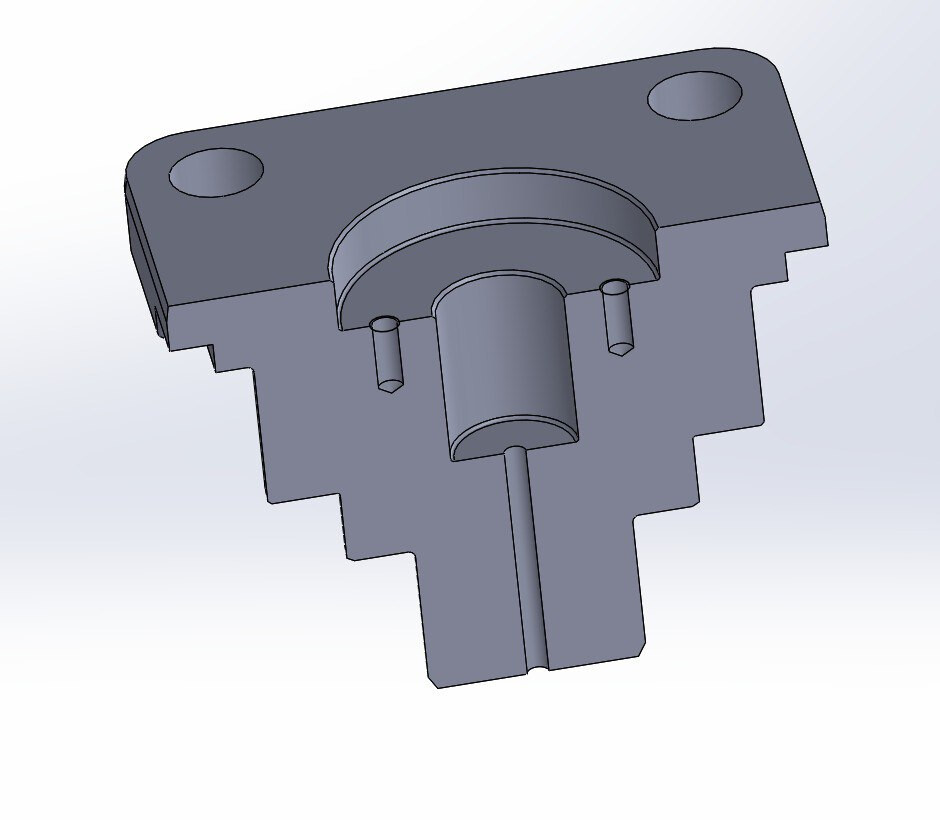
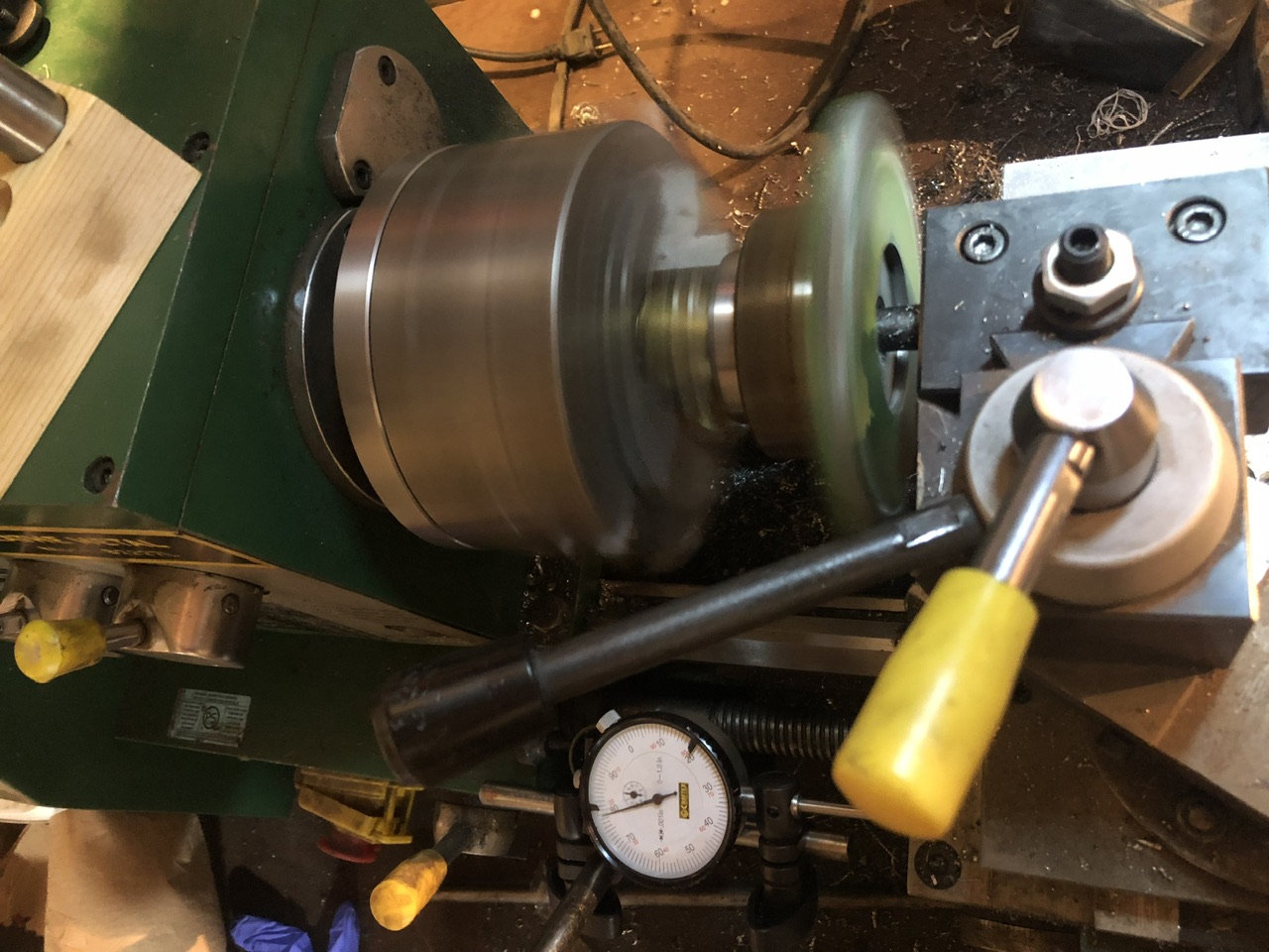
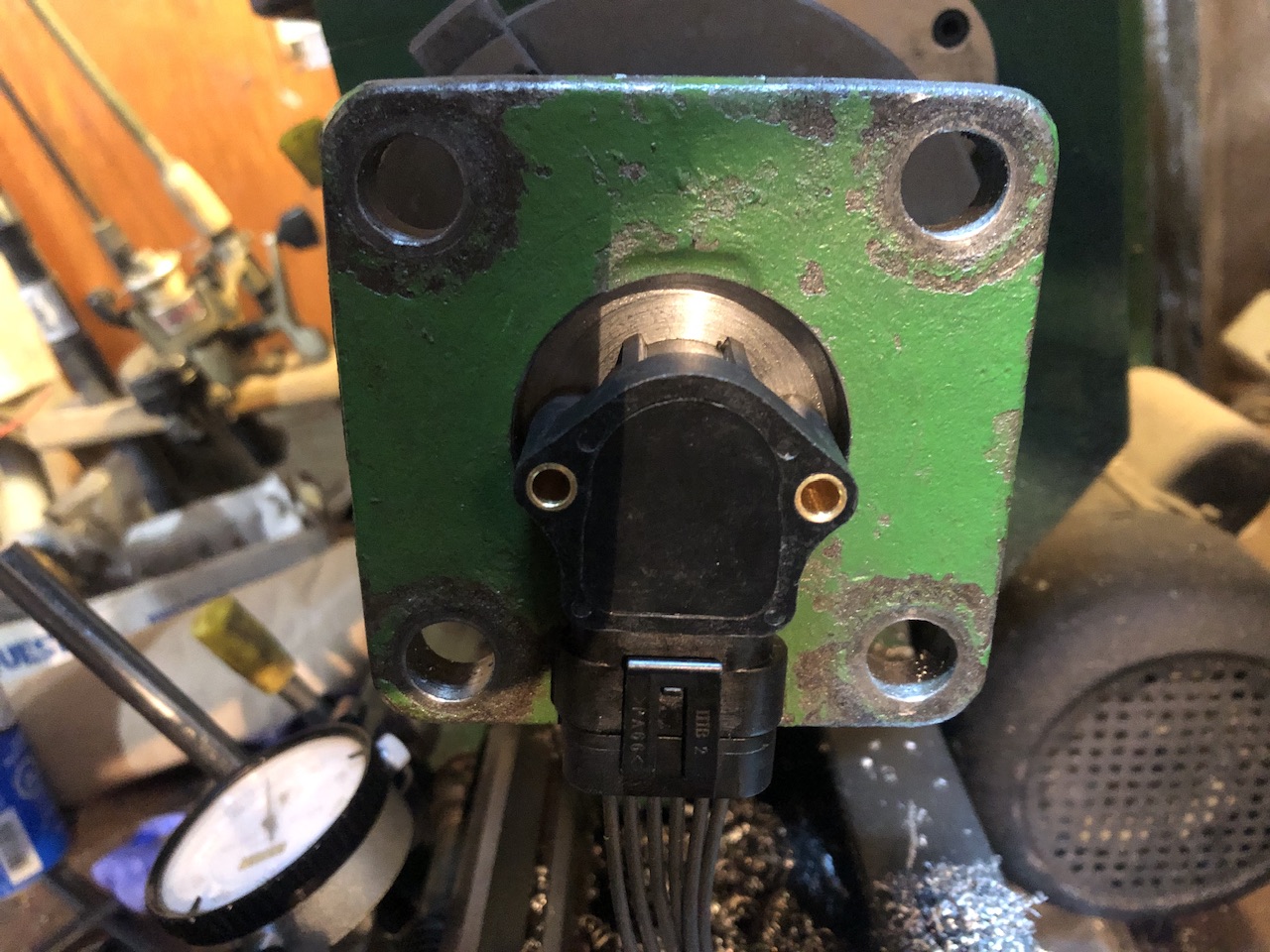
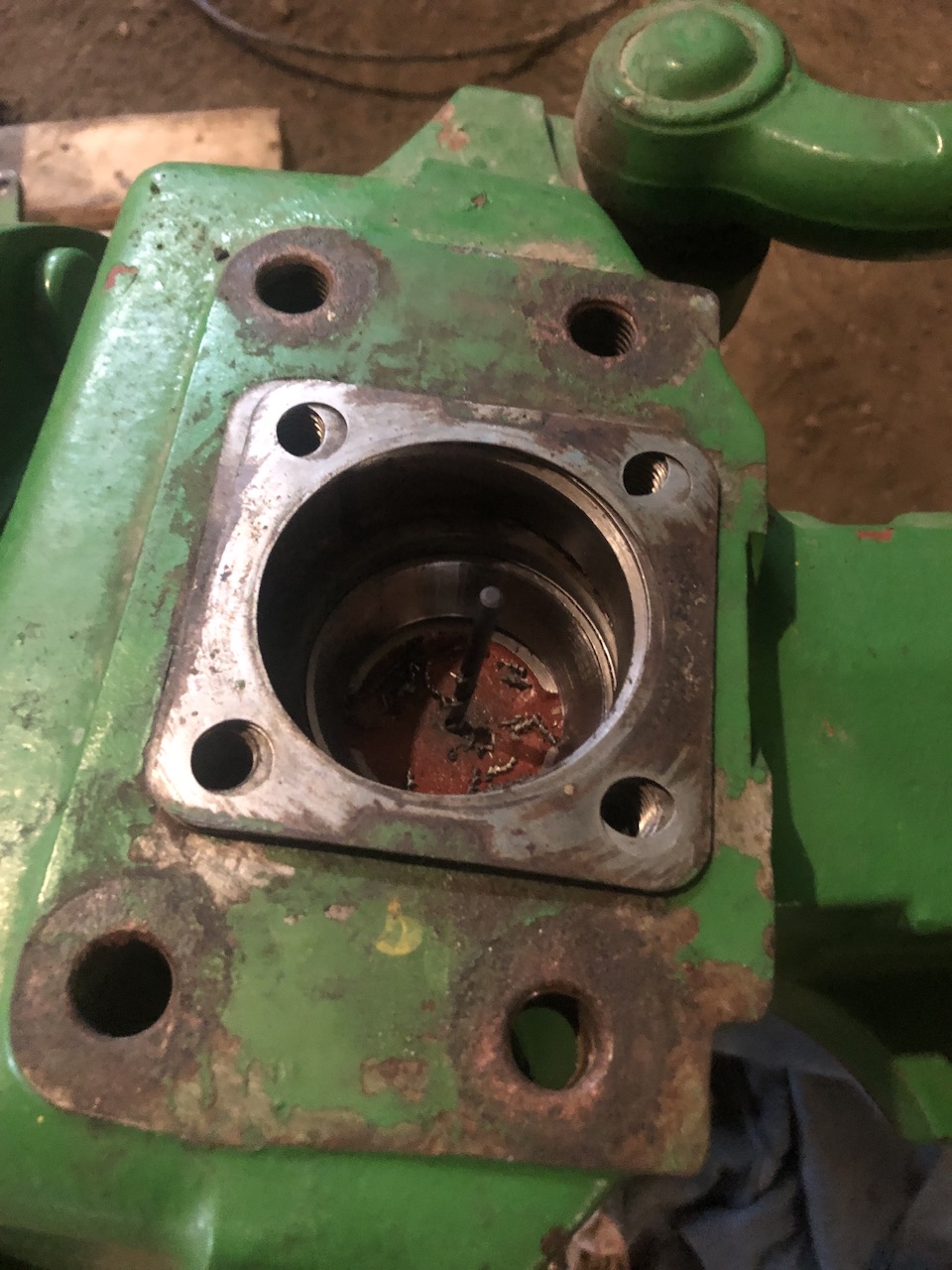
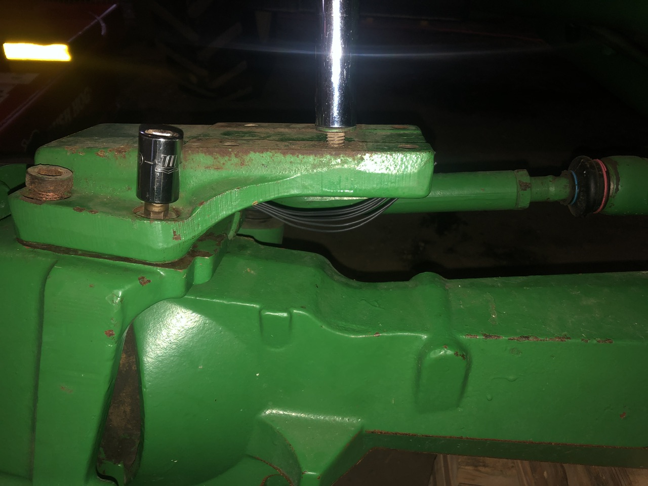
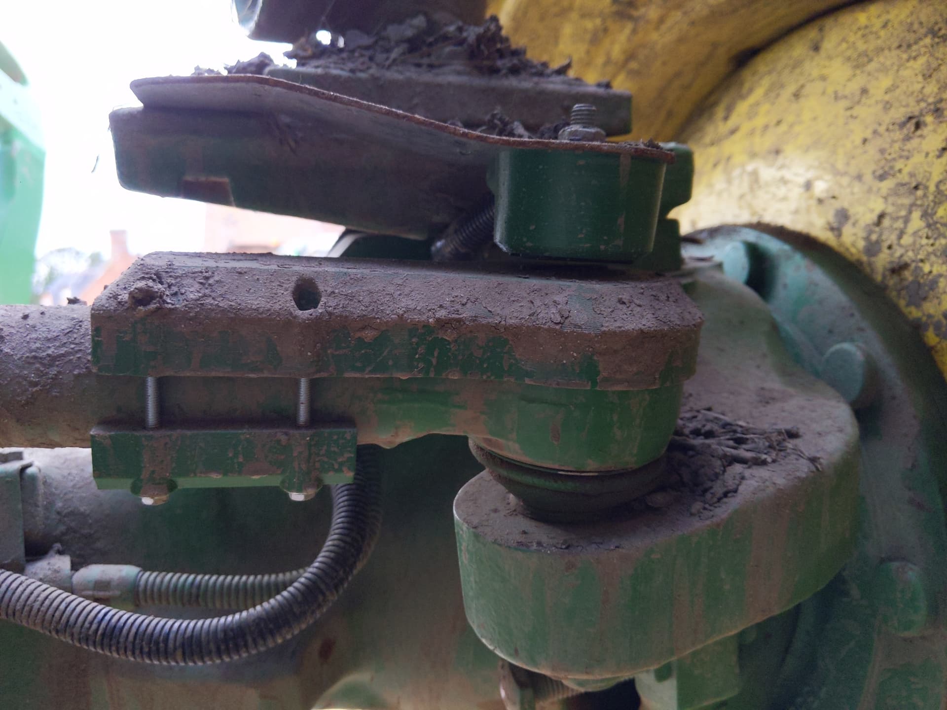
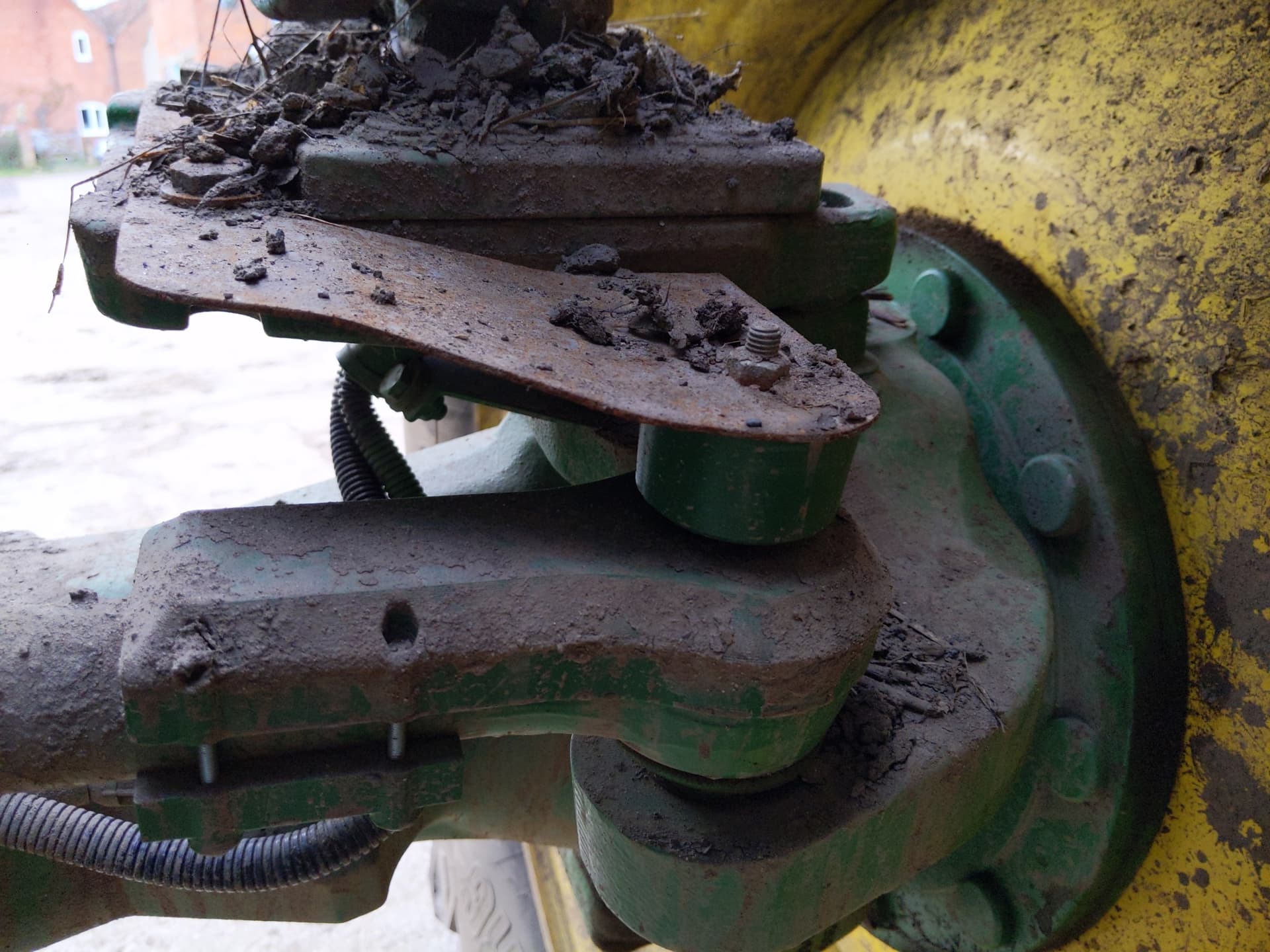
My John Deere 7410, machine for Deere spring loaded angle sensor. A small 3d printed adapter and allen key complete the mechanical connection.
5 Likes
Hello,
This is the John Deere sensor, Deere RE575331, or equivalent aftermarket sensor, you have used here?
After reading the wiki on wheel angle sensors, I bought a similar sensor, not original Deere, but should be a replacement part. I liked the fact that it is spring loaded, but was surprised when it arrived, that the sensor have a 180 degree range (both mechanical and electrical it seems to me).
I instantly knew it would be impossible to use the whole 180 range as a WAS, but tought I could atleast arrange something that would get me near the full use of the range. This proved to be harder than I first expected, so now I am thinking it would be much easier to use much less of the range.
In your setup above i expect the range of motion to be somwhere around 90 degree, am I correct?
Is your sensor also a full 180 degree sensor?, and if so, is it accurate enough used at only about half its range?
This is the A&I version of the Deere sensor, it is indeed spring loaded with 180 degrees of range and the installation uses only about 90 degrees.
The tractor is sitting in the shed with all the panels off waiting for a valve and harnessing, so I have not tried driving with it yet. This sensor is fitted on many Deere tractors in the kingpin and there are people here using that sensor by reading only 1 signal (sensor powered by Deere harness and AOG reads 1 analog signal). I believe Baraki also sells and installs this sensor.
In my case, I am going to wire the sensor for both analog signals and use the ADS on the AIO board in differential mode.
So I’m using half the effective range of the signal, but reading both signals should double the precision. That should cancel out and I expect that to work well. From there I can try reading only one signal and seeing if that is sufficient, I expect that it is, since others must be doing it.
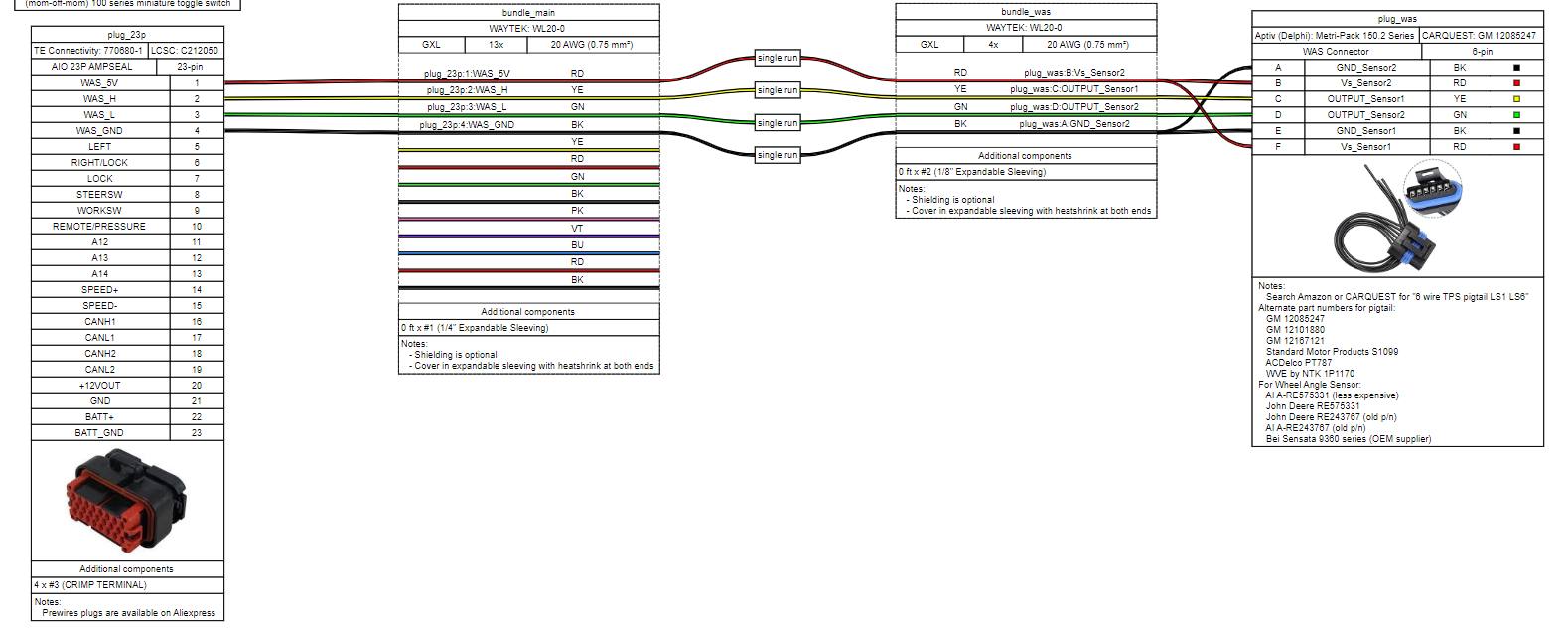
This harness schematic is a work in progress but it has all the alternate part numbers for the sensor and part numbers for the pigtail, so maybe it’s of use to you.
1 Like
Thanks for your reply.
I had no idea both sensors signals could be used at once. I hope you will let us know when you have tested, if there is a significant difference between your two or one sensor setup.
1 Like
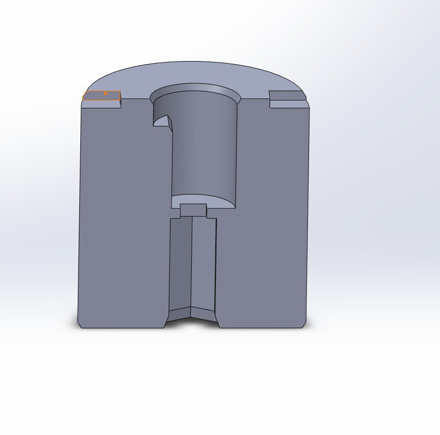
I love this installation. I am will be doing this next winter, do you mind sharing the STL for the adapter?
1 Like
Thank you for the compliment. Please find the file attached, for 1/8" allen key. Print with hex side down, no supports. I’ve included the solidworks file in case you need to play with sizing.
WAS_HEX_Adapter.zip (163.8 KB)
Rotary hall effect sensor with a separate magnet, that is fixed over the top of the track rod end.
I printed a holder to hold the magnet in place, but would probably just glue it down in future. The main part of the sensor is set into a printed housing, which helps protect the fixed wires coming out of it. I would have used a Honeywell RTP, with a plug on the sensor, but they have more than doubled in price in recent years.
2 Likes
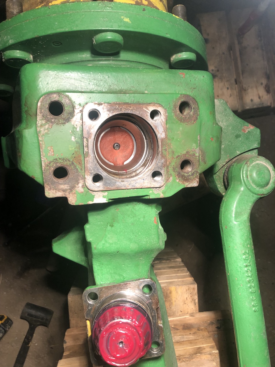
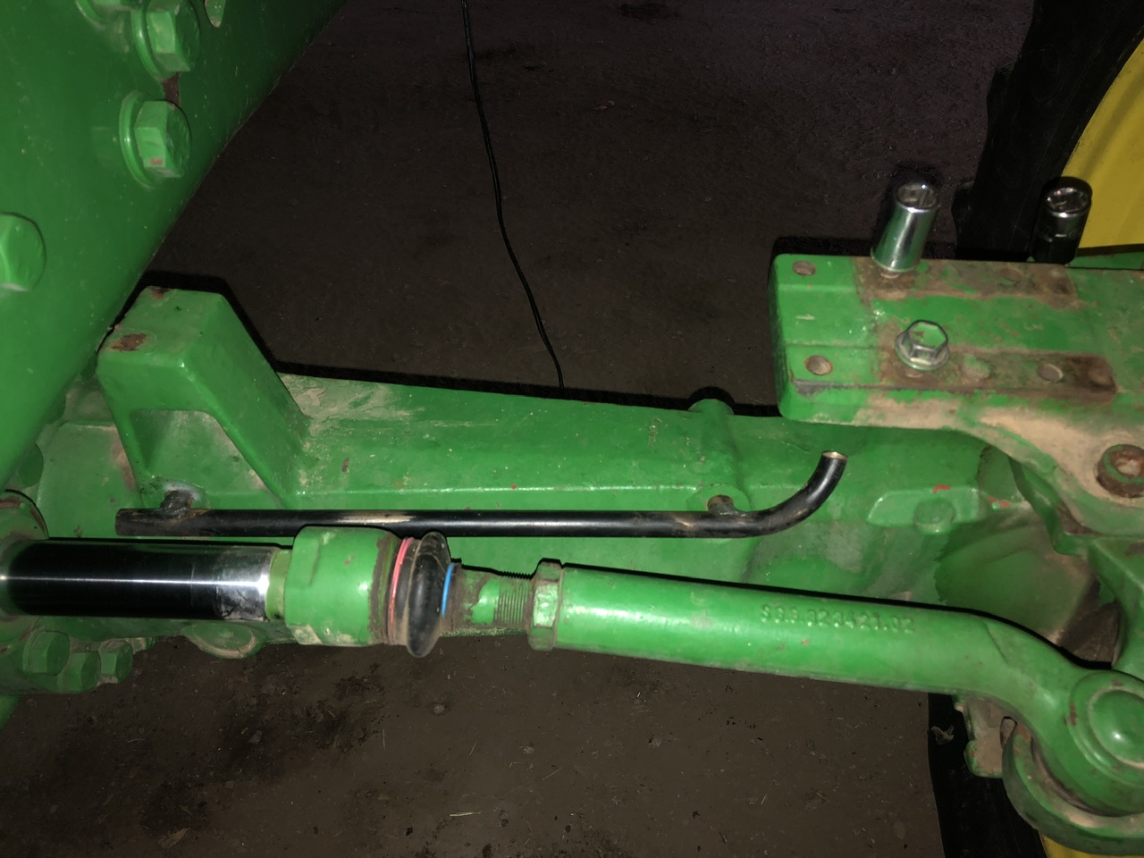
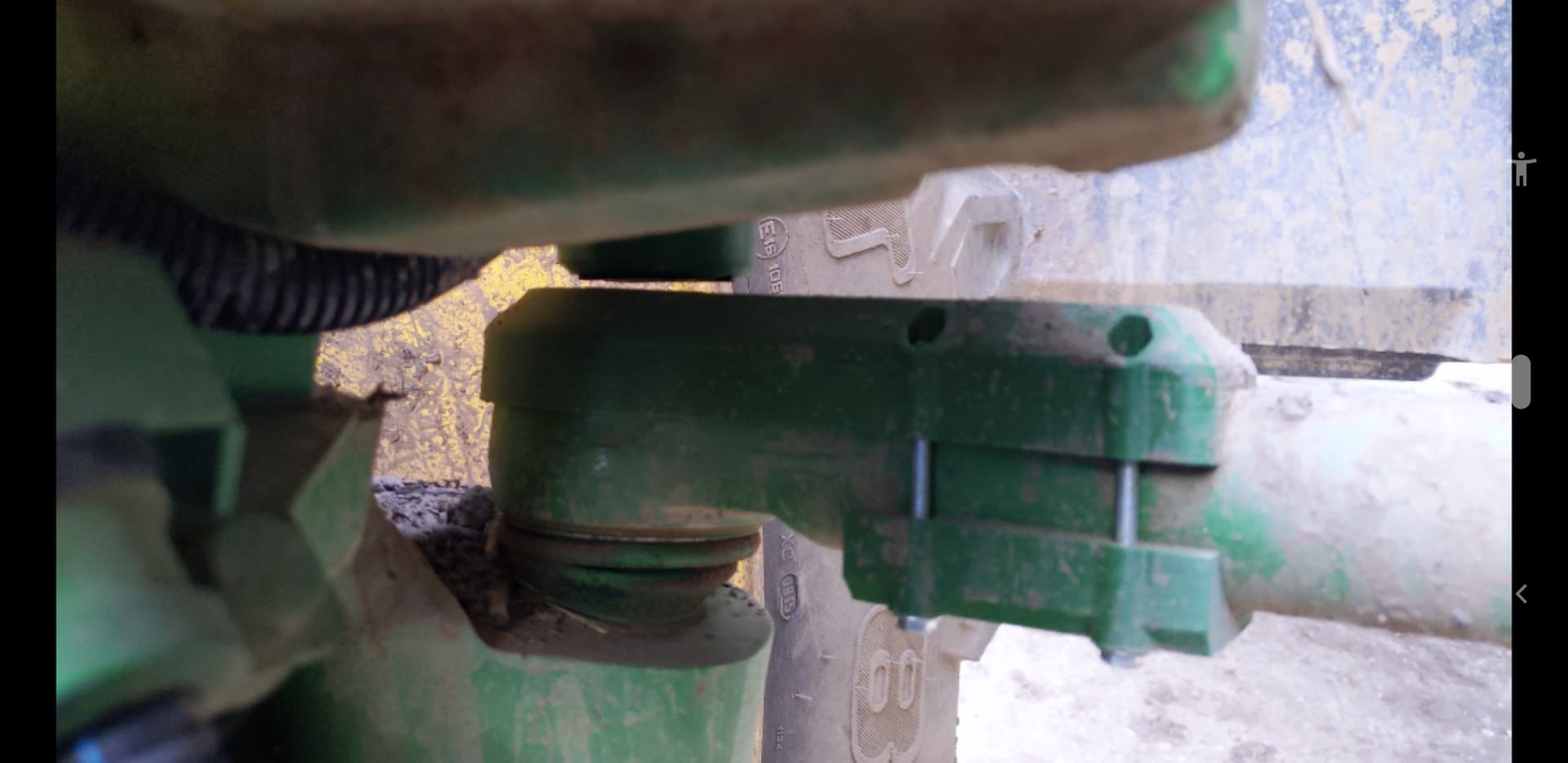
Hi! Does anyone know a tip on how to install the sensor with this type of suspension? Unfortunately, the steering cylinder piston rotates around and displaces the sensor, and all other parts move on bumps…
is there room over the main cylinder body for a linear sensor?
mayby i could fit it. But the problem is that piston(that part that moves inside and outside from cylinder when turning) has free rotates around itself and does itrandomly during use (also I can grab it with my hand and turn it around) so it will damage the sensor. I made rotary sensor instalation and it worked well except for problem with the piston rotation - when this happens the rotation of the piston affects the reading.
Just have a look at the first post of this thread! Many usefull examples of that Carraro Axle there!![]()
sure before posting i look at whole thread, I also looked for tips in other topics and places. To be honest i didnt find many examples installations on this type of suspension but mayby i didnt see or understand something. Could you be more specific?
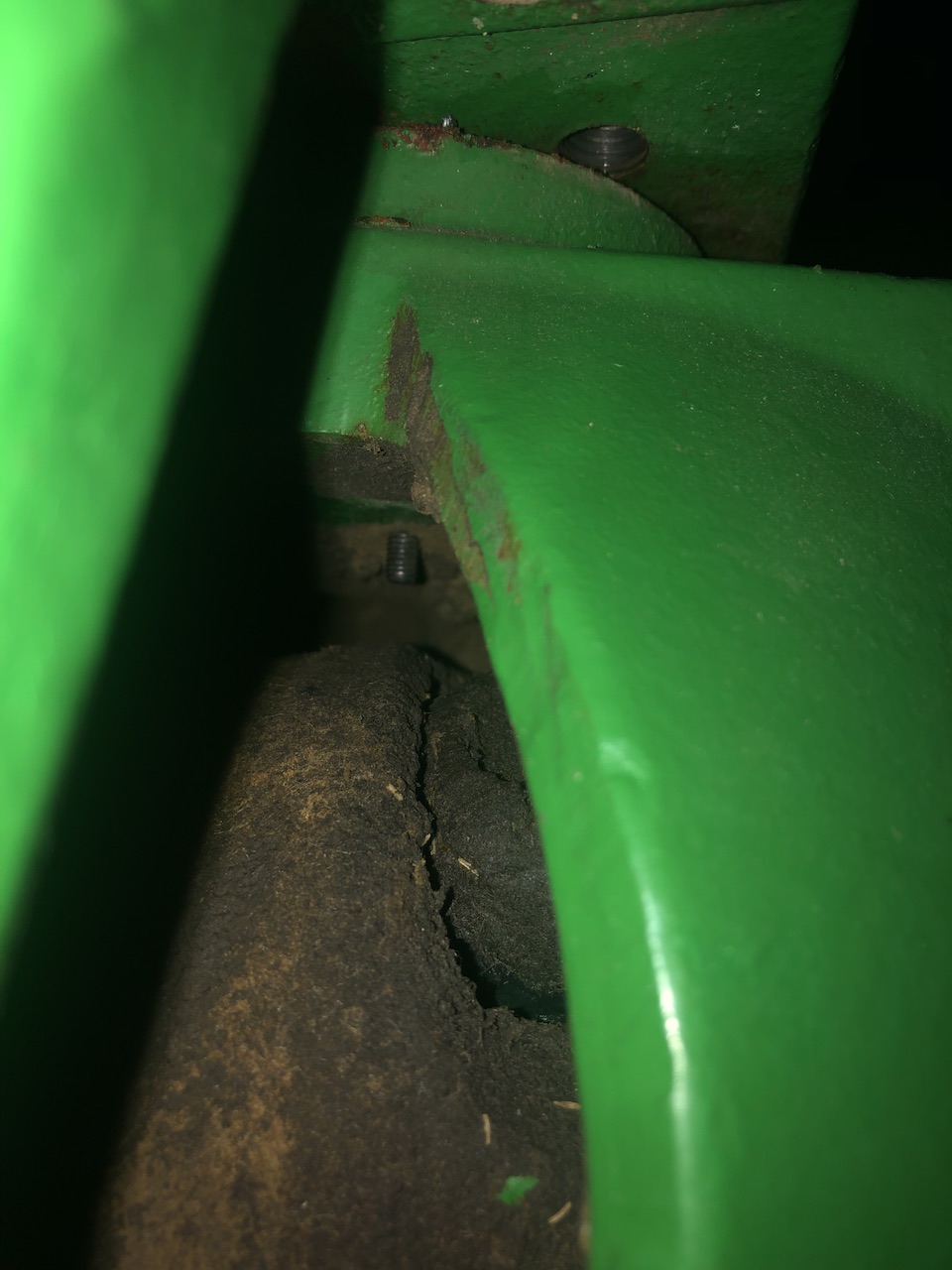
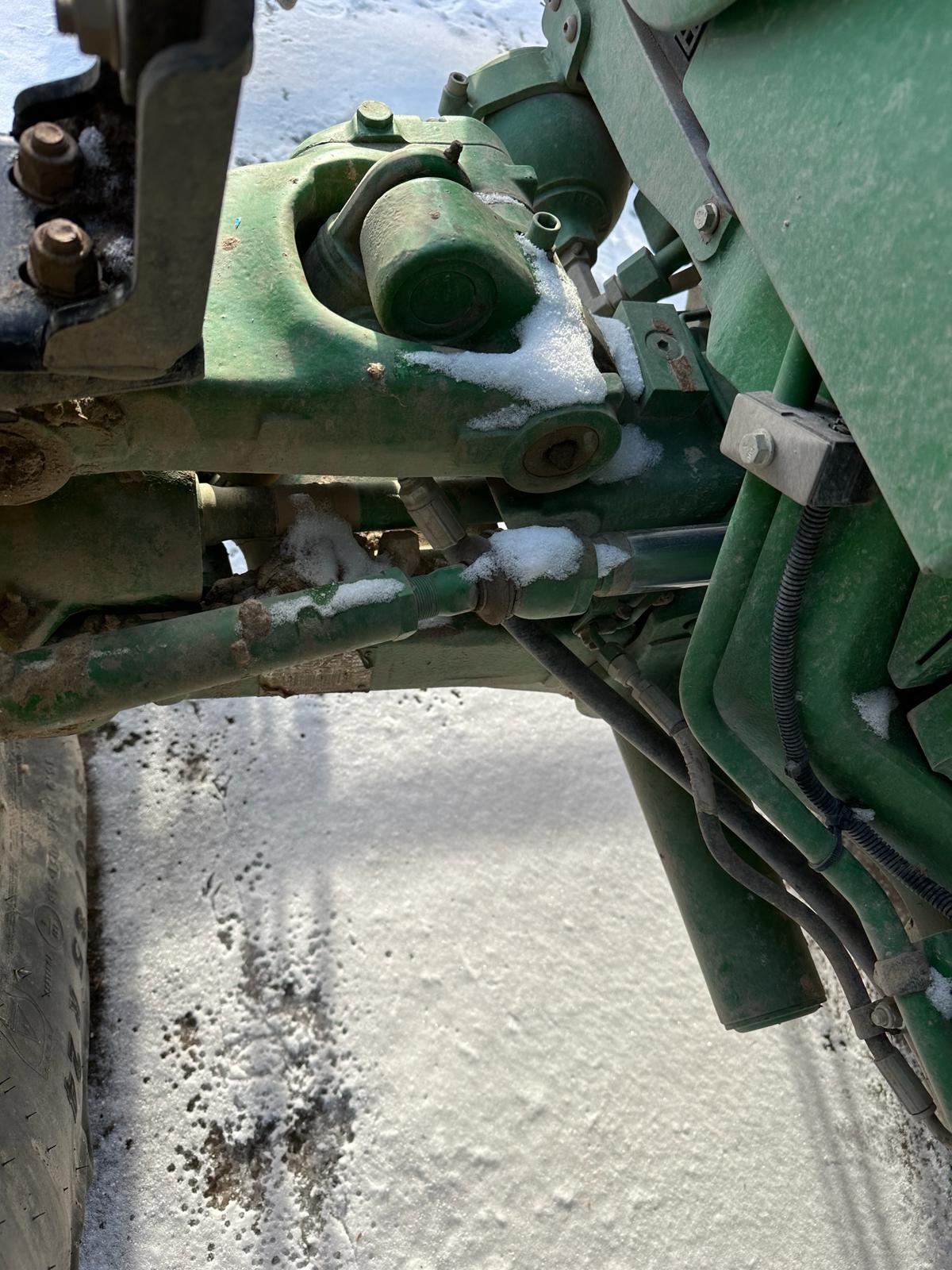
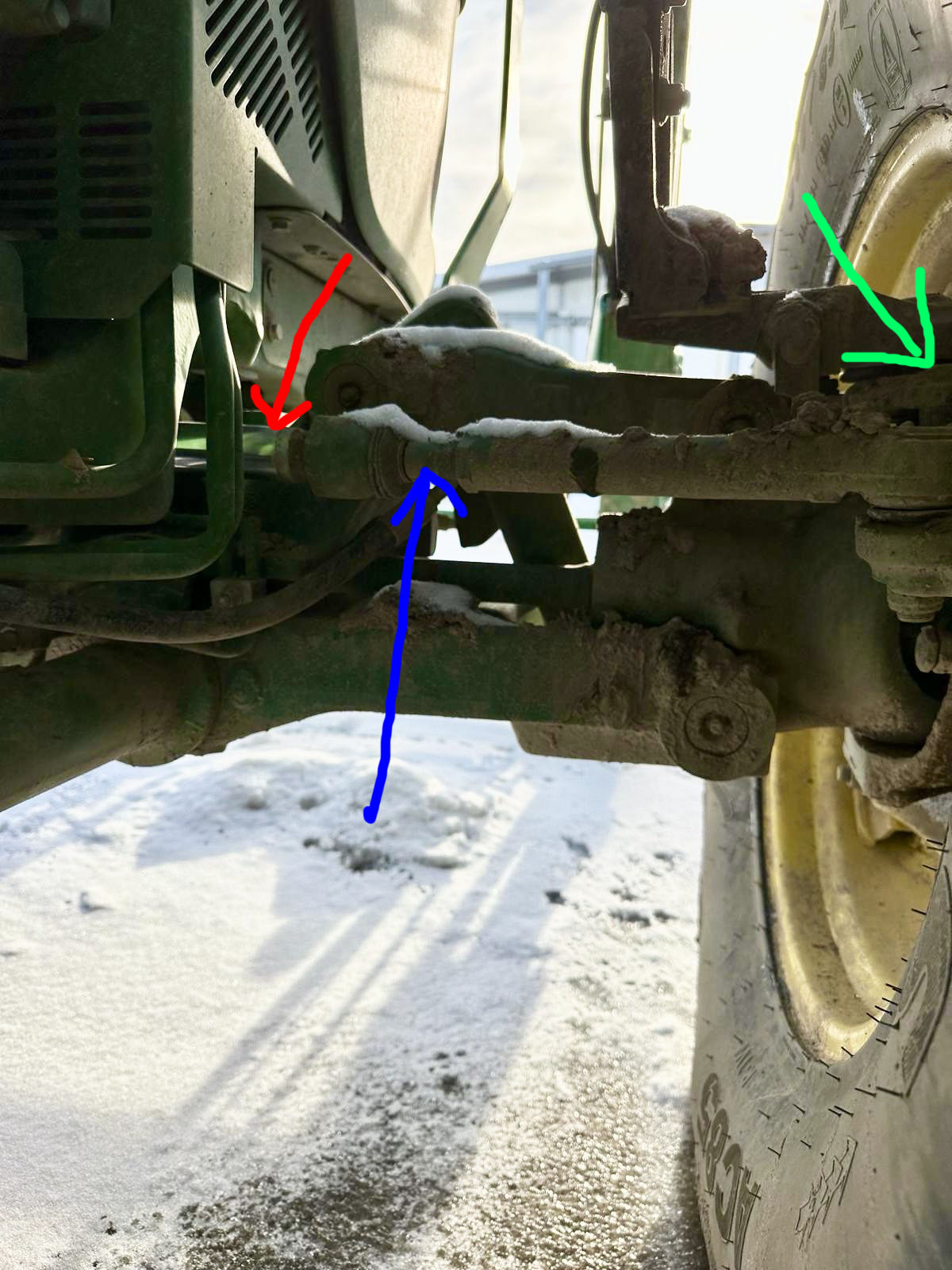
I could find many instalation (linear or rotary) to part that i marked with red arrow but i cant do that - this parts rotates around which distorts the rotary readings and will damage the linear one. It would be perfect to use the part marked in blue because as it is already behind the joint and no rotation on it, but on every bump this part moves up/down and in other directions, which also affects the sensor.
In the examples I found major modifications to use the location marked green (from what I know, the original sensor is located there if there is one - in mine there is no space for it so I would have to make a lot of modifications ), and from what I can see it is a very large modification requiring a lot of skills and equipment which is beyond my scope.
I hope that maybe someone has another, simpler solution…
1 Like
does the part exactly half way between the blue and red line turn also?
do you mean the thicker green part? joint housing? yes, it turns with the piston. There is rubber at the end and then the part marked in blue comes out.
Does the part behind the green arrow move? Can you take a shot from above and behind?
yes, it whole moves together with the fender, i’m thinking the way i attached photo is only possible at green mark but as i told it reqire lot of skills ![]() Unfortunately, I am not able to take a photo at the moment because I am not close to the machine, but I will try to take one and add it.
Unfortunately, I am not able to take a photo at the moment because I am not close to the machine, but I will try to take one and add it.
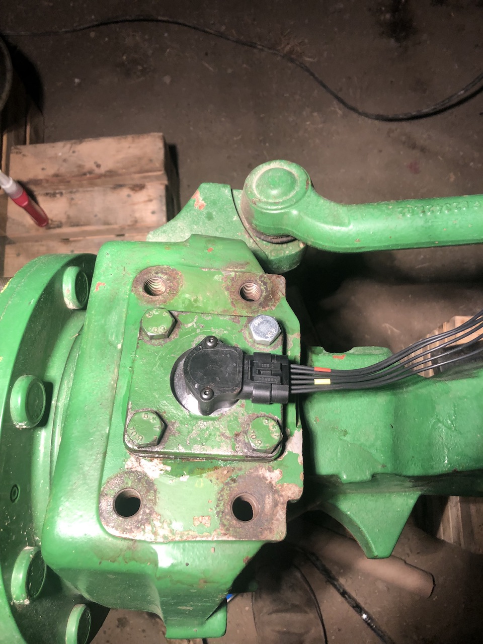
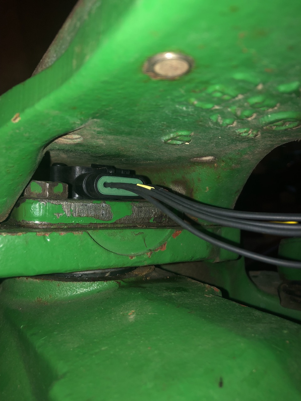
i mounted mine to there,it has the potential to turn but ive never seen it turn
post 12 on this thread is my instal
Have a look at picture in post 6. This is how I have mounted sensor on these type of axles.
Unfortunately, in my case it turns, I did a few tests to check it