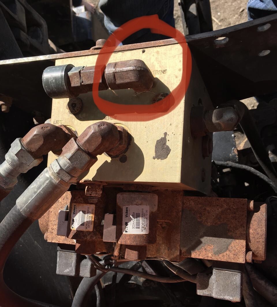
I have an aog setup on my articulated sprayer and am trying to adapt it to a NH 8970A as well. Does anyone have an electrical wiring diagram for an eaton vickers mcd 8632 valve. I believe it is this valve MCD-8632 EATON - VICKERS For Sale in Fort Dodge, Iowa | shop.thegatorcenter.com (hard to read off the valve) it was installed on the tractor along with a wheel angle sensor when i bought it, but all the electronics and computer were removed. The hydraulic side is all hooked up but is isolated from the active hydraulic system.
Any help would be appreciated thanks Roger
Hi
you can search “Vickers” on the forum
The electric side should be easy to connect, we just need to discover what the 2 little solenoids do, do they are just active when autosteer is on?
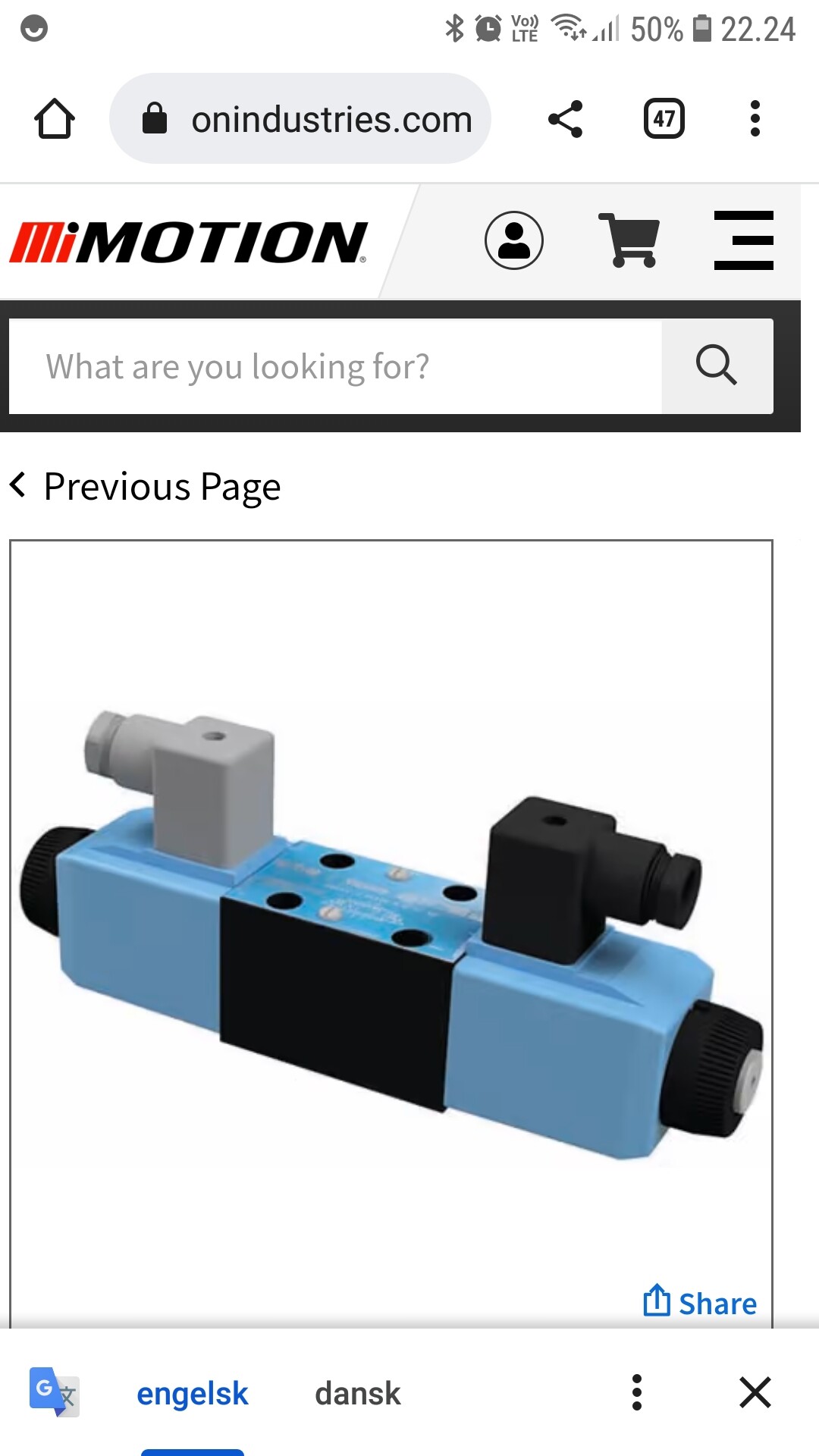
I have been using an eaton valve like this one in the picture. I have it connected to the cytron with a 24v converter, motor A and ground to one side and motor B and ground to the other. Seems to work🤷♂️
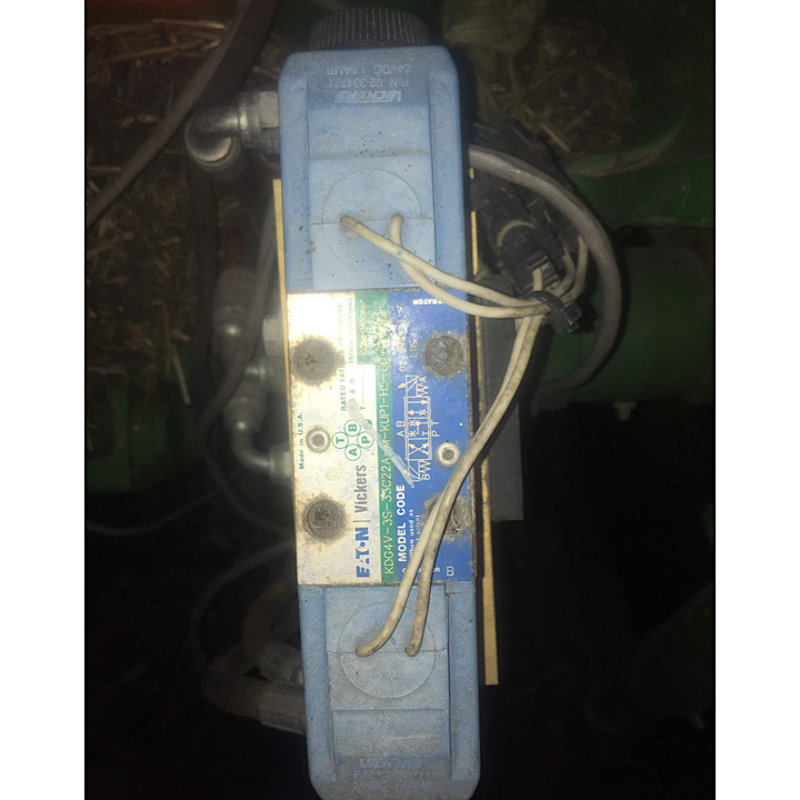
Edit: but the one you posted looks a bit different than my setup, so it might not work the same way
I was going to use a cytron MD13S board to drive this, If this will work. how do i wire this to the two motors and two solenoids? Thanks
ya i’m not very knowledgeable on this topic. In my unprofessional opinion, it looks the valve that you have linked, the main steering coils look about the same as mine. On mine i essentially just ran a wire from Motor A on the Cytron to coil A on the valve, and connected it to one of the wires coming from the coil and the other wire i connected to ground. As far as i know, polarity is not important when connecting the wires to the coil, correct me if im wrong, its been a while since i did it… then did the same for the other side—Motor B to coil B on valve block.
Now as to the rest of the assembly that you have linked to, i am not sure what the functions of those other coils are, i don’t have anything like that on mine.
hopefully i am making a bit of sense, or someone smarter than me will be have to help you…
After doing some testing - we have figured out the following the two motors are used to turn the machine right or left. the two solenoids are just for isolation when autosteer is not being used.
My next question - is there a way to power the solenoids from the control arduino using a relay? currently i am testing the system by using a separate 12v switch, the solenoids require 12 volts to hold them open and 0 volts closes them.
Another option would be to do something similar to the spray boom control using a separate arduino I think?
any help would be appreciated. thanks rmca
What you are looking for is the output named aux hydraulic relay (available both for cytron and ibt2)
See the steer. Png and other schematics in support folder. Same relay as what we use for 6/2 cut off valve.
or google: arduino 5v relay high level trigger
High level because it is 5V to activate (5V output from autosteer PCB)
If you have got a Kaupoi autosteer PCB ver4.1 then there is a SW out, which will be 12 V, only when automatic steering is on. (controlled by a Power fet BTS442E2 )
What you name “motors” are actually the right and left solenoids on a ordinary vickers proportional valve.
Hello,
I’m new to all this, did a few with electric steering but now got to one with one of those Vickers valves, did you already figure the whole wiring out so could help me out?
Hi Folks
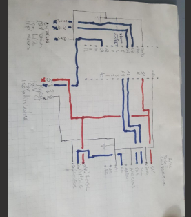
I have an eaton vickers valve like this one MCD-8632 EATON - VICKERS For Sale in Fort Dodge, Iowa | shop.thegatorcenter.com The solenoids (the two brass looking nuts are on top of these) are just isolation for when autosteer is not in use. I am using a nano board, MD13S cytron board to drive the motors, an ADS1115 analog digital convertor from the wheel angle sensor, and a single channel relay to control power to the solenoids. From the nano the signal to open the solenoids comes from D9 to the relay which is wired normal open and closes when the autosteer switch is pulsed. The cytron is driven from D3 to PWM and D4 to DIR it has 12 volt power input and an output to each motor (the black box type on the right and left side of the hydraulic valve) The solenoids and these motors each have a ground as well. Mine grounds are all wired back to the box into a common ground from the tractor battery. I tried to attach a sketch of the wiring hopefully it comes through.
Good luck
Alright, thanks
Think that will help me a lot,
When in comes to Steering performance do you configure it just as you would for electric motor? I mean like the Min Low and Max settings for how responsive it reacts.
It has been wet here so I have only got to the field for a few hours, current settings are P 103, Max 203, Low 91, Min 40. I think that it needs some more tweaking but we won’t get back in the field here for a few days yet.
Good Luck
Alright, do you open both valves at the same time when activated Autosteer or just right and left depending which way it wants to steer?
It must be the two solenoids under the brass nuts you refer to. So Yes both must be active when autosteer is on. Also see original text above.![]()
But the cables to the Right and Left Solenoids have 3 wires in them!?
Use a multimeter, and check if one of them are direct to ground. The two other should have connection with some ohm
Which one of the other two is 12v then? To me the blue one is Ground
Either of them will work. But test with a fuse. Use the two that have some ohm between each other, one end to + other to - the third one does not have to be used.
Test both sides to hear some click from inside.
Blue to red moves something but with no ohm and blue to yellow sparks and gets hot (but has ohm). I’m doing something wrong?
Take off the connectors, underneath you see 3 pins, the two at sides are the ones you use, the middle is supposed to be connected to body, and not used on any off my spool type valves.