What printer do you have?
anycubic i3mega
So modifying the cytron board seems to me to be the better way, no relay, no extra cables.
1 Like
205 max you need a new desing
great thank you, I don’t know how I managed to miss it…
several newbie questions.
1:
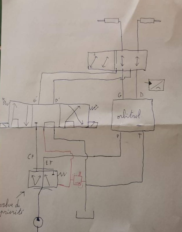
My hydraulic system is going to be consist of the following.
- a 6/2 valve to switch to orbitrol output and proportional steering valve.
- the proportional valve in 5/3 (loadsensing output which will control a priority valve)
- a shuttle valve on which a pressure probe will be connected between the right and left exit of the orbitrol in order to regain control of the autoguiding
so if I understand correctly I could control my 6/2 valve with the MOSFET HSP0115 with the PWM2 control on the LOCK output.?
for the pressure sensor, you have to wire it to pin 10 of the AMPSEAL23 connector and make a bridge on the PCB between “PRES/REM” and “PressureSense” so that the signal is processed by pin A10 of teensy.?
thank you
I think that is correct.
1 Like
Maybe you will take advantage of my offer. If you want to assemble from pieces, the 3/5 valve is not a good solution for AGO.
why do you say that the 5/3 proportional valve is not a good solution for AOG.?
I designed and had my hydraulic diagram approved by the hydraforce technician in my sector.
the hydraforce valve in 5/3 already equips several AOG systems to my knowledge and does not pose a problem. my orbitrol is an open center type with force feedback, which was the hardest thing to solve was to regain control over the direction.
I’ll give you the schematic.
1 Like
great thank you.
how is the +15V generated from the +12v in.?
do you think it can deliver a power test without overheating the PCB to power my CF-D1 tablet whose original charger delivers 15.4V?
15 V is just to indicate it is not regulated by a 12 v power source. So 15 V is the battery voltage when tractor engine is running and normally would be around 13.5 V
I believe you can also say it is a way to see there’s two different 12 v power supply.
OK, thanks,
I didn’t understand the schematic.
the 15v output can therefore be used to power my pressure sensor rather than splicing the 12V-in.
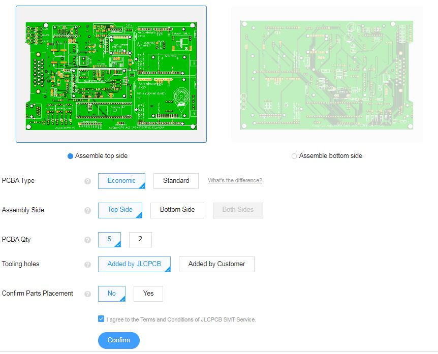
I’m going to place an order at JLCPCB, it’s a first for me.
for the pcb assembly it says to leave everything as default. there are no components on the underside.?
I leave everything as in my screenshot.?
thank you
Is there wiring diagrams?
There is some inventory shortages, what are these parts used for?
onsemi CNY172M
Monolithic Power Systems MP1584EN
PANASONIC EEEHD1E102AQ
Texas Instruments TLC081IP
Microchip Tech MCP2562-E/SN
how many of each is missing.?
optocoupler for the speedpulse output.!!
3.3V voltage regulator for the can bus chip
surface capacitor 1000µf 25v
certainly those used to smooth the current in the power input part
OP amp use in motor/valve control
micro use in communication Bus can
The 1000uF cap is the only thing missing that you need providing you are not using a Danfoss valve or canbus.
You can use the same through hole 1000uF capacitor that is used on the original V2 autosteer board.
1 Like
Is there anyone from Europe who has ordered PCB’s (micro AMP) and has spare one which he is willing to sell to me? Only need one for now.
Yes that would be possible.
BUT:
We need to have a specific explanation on how to power the cytron, as I don´t understand how that should be done.
The 12V In is not enough because it passes through the D2/D6 (which I believe is for reverse power protection, and has max 3A) and then becomes the +15V line.
Maybe the +15V pin at AMPseal is also for Batt in, because the Lock mosfet HSP0115 is also powered from the +15V line?
If so, then D2/D6 is not needed.
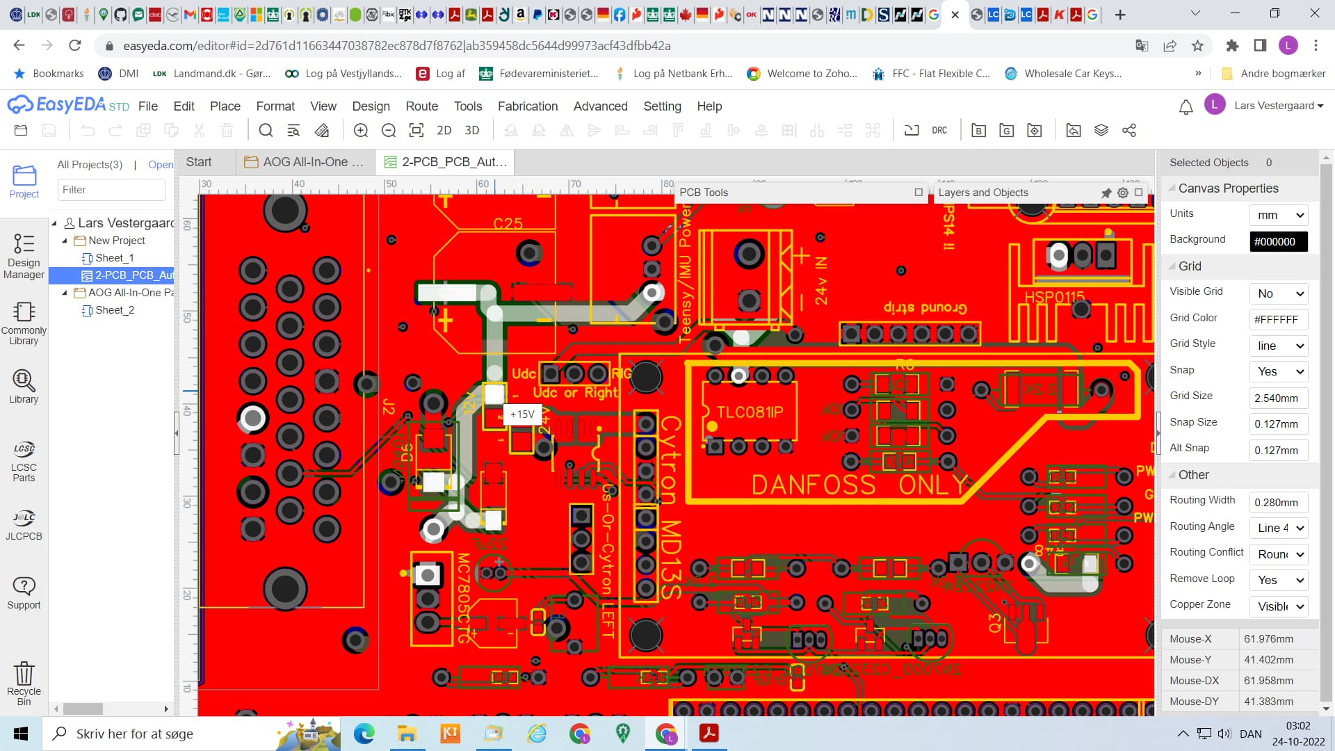
I think if you need more amps, use the on board 24v input. Might be nice if it has a pin at the connector. Configure the solder jumpers.
Agree ![]()
One of the 3 GND could be changed to that purpose.