I’m searching for a fitting connector for the factory wheel angle sensor on my JD 6120R. I like to build a Y-cable to put in between the connector located in the middle between the front wheels. Does anyone know how this connector is named or where to buy them?
Thanks for your quick answer!
So you think it could be CAN? I have to find that out I think…
Edit
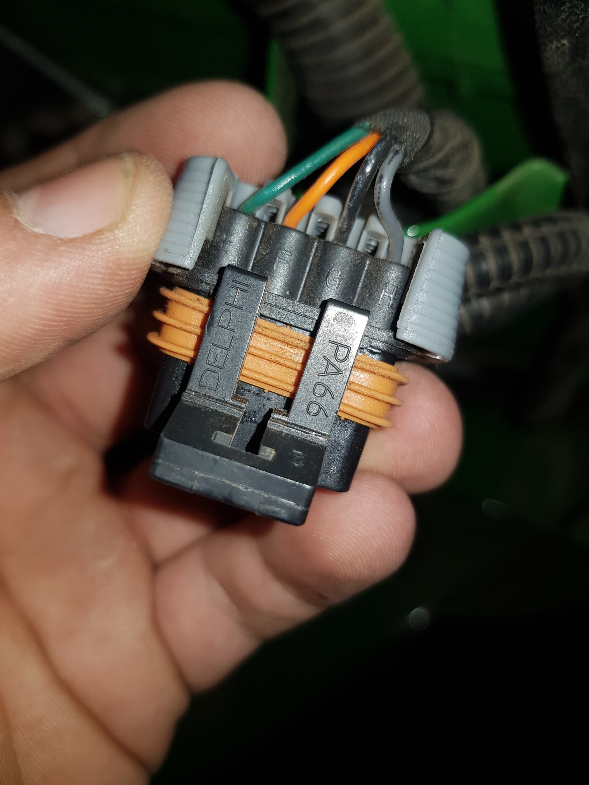
Some measurements on tractor side of connector:
I measured the voltage from pins to ground… There was only one pins not 0 with about 4.9V
I also measured resistance to ground I found the ground pin.
If the other two pins were CAN, there should be some voltage on them, right?
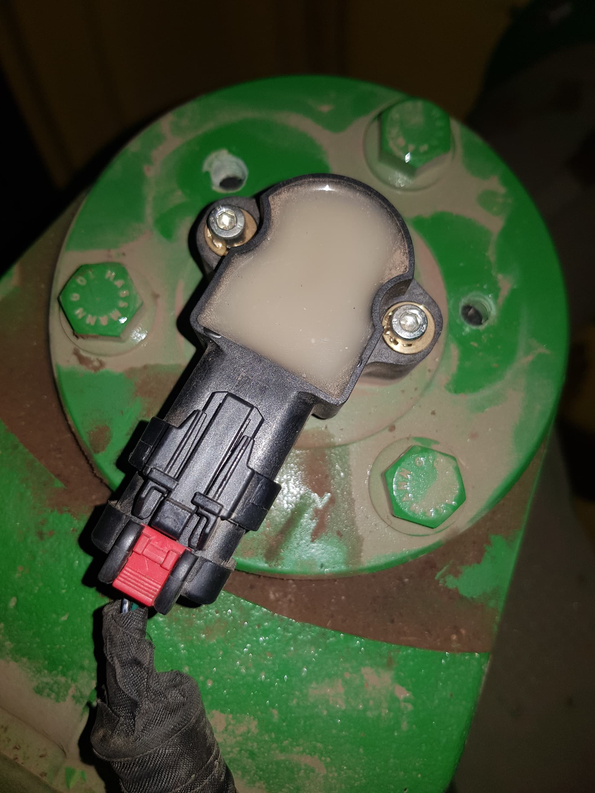
Nope, CAN can work only on 1 wire, second CAN wire is used for communication safety. But in your case, probably it’s not CAN. Have you got sone image of sensor? Mayby in that way we can find out pinout
Hello, below is the electrical diagram of the angle sensor on the 6R tractors. It’s the B139 at the bottom of the picture on the right. The signal has to be collected on the WAS Sensor CH1 Sgn IN. This is number 2 on the socket. To control the signal you need GND (number 3) and CH1 (number 2). You should have a range between 0.5v and 4.5v.
I have to try that the next days…
Do you maybe even know, where the next connector shown in your picture (“X637”) is located on the tractor? I would guess its near the cabin and a bit more comfortable to use? For now I couldnt manage to follow the cable from the WAS to the cabin…
Impossible for me too to follow the cable to the cabin… So I took the signal directly from the angle sensor. For the moment I only take the signal on the CH1 SgnIN (purple wire, number 4). It is absolutely necessary to check that the signal is stable. If it is not the case, you have to supply the sensor with power from the PCB.
I looked at the diagram, it looks like the sensor is duplicated, double. For what purpose? For safety in the event of a failure 1 of 2? Maybe detaching 1 and using it to AS will not cause an error in the tractor.
@jdros I only took the purple wire of the signal I plugged on my PCB. I left the tractor power supply on the sensor. But on some tractors the power supply on the sensor is not stable, so remove the tractor power supply and supply it from the PCB (Vcc and gnd).
@baraki I tested the second CH2 signal (blue wire). I noticed that the voltage range was divided by two 0.25v to 2.25v. I don’t know what this is for the john deere GPS.
I believe, that this sensor works betwen 4-20mA. 2nd channel is for calibratio, I mean when you replace sensor you need to calibrate sensor (such as in Challenger Rogator). I may by wrong but it seems to be that solution.
They are in the diagram as potentiometers. Calibration is about saving the correct values in the ECU and not in the sensor. I have an autotrac manual in which the sensor (with 3 pins) is additionally mounted, it’s the same procedure
I did not have a stable sensor power supply from the ECU in any tractor. I also connected the power supply from the autoster and the signal in parallel to the ECU and the autoster. Works in NH, Case, Claas
Sounds odd if the voltage source from the tractor to the sensor is not stable. It really sounds like the sensor would be working in a 4 to 20 ma current loop mode as kurak mentioned. Then again, supplying power from AOG board to the sensor should not work at all for a current mode sensor.
There were other tractors where the sensor was drawn as a potentiometer in the circuit diagram even if it was a 4-20 mA current loop sensor. Be careful out there.
Disconnecting one of the two redundant sensors sounds dangerous. The tractor should not switch to the one that seems to work but it should abandon the WAS signal completely (assuming standard redundancy implementations). Not that catastrophic if the sensor was only used to control 4 WD on turns or differential locks but not so good either.
Interesting to follow what everyone finds out on the topic.
I have a 6130r that I want to use the factory WAS, unfortunately the images have not migrated from the old discourse forum, I feel they might have shone some light on what I was needing.
I have traced the wires back to a plug near the axle that has 4 pins. Have people disconnected this and then fitted your own plug with 3 wires going back to the PCB, what pin out did you use for GND, VCC and sense? Was using this sensor successful?
On my 6930, and 6210r I used a landrover suspension sensor, so using the factory fitted one is new territory for me!