Hello guys,
i just wanted to share my experiences with AgOpenGPS on my steering ready Massey Ferguson 7718 tractor for beginners. With Tonys (CommonRail) Arduino Program, it is no rocket science to get a working solution.
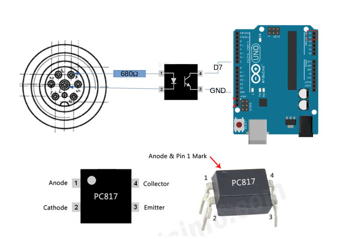
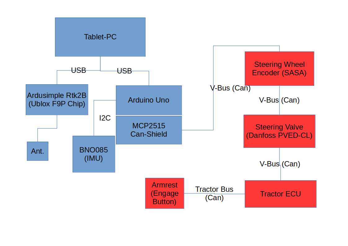
Basic wiring scheme:
Hardware and beginner issues
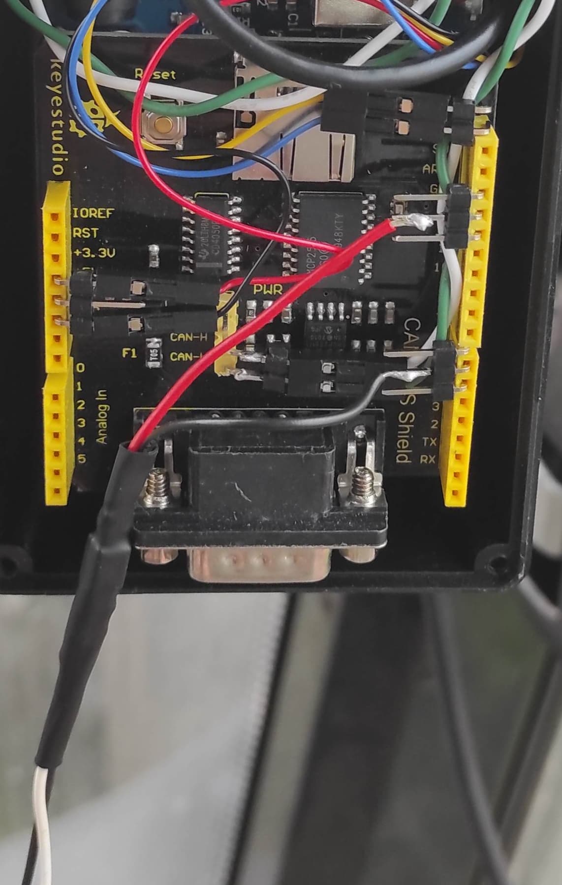
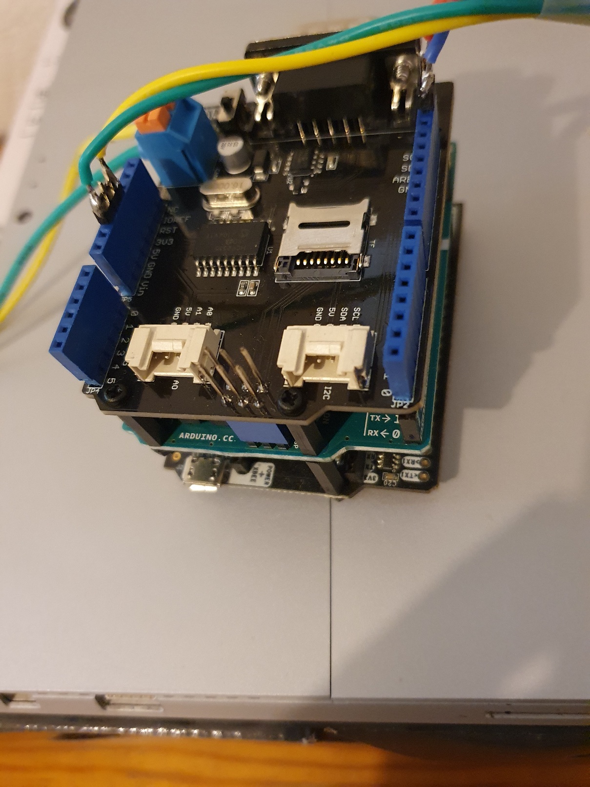
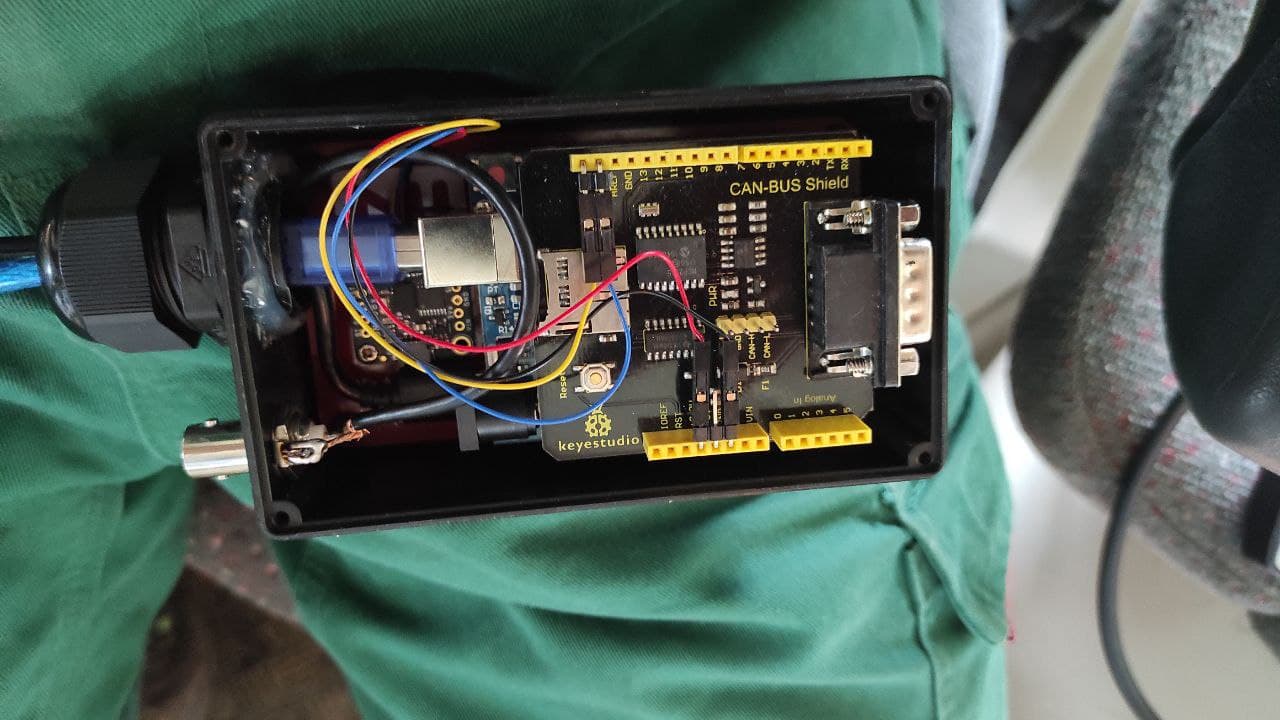
I recommend using an uno and a bigger can shield, because you can easily snap the shield on and you have a shock-proof connection. A nano and the little can shield might also do the job. My fake arduino has (as many others) have a CH340 USB to TTL converter in them, so you need to install an extra CH340 driver to let windows establish the connection.
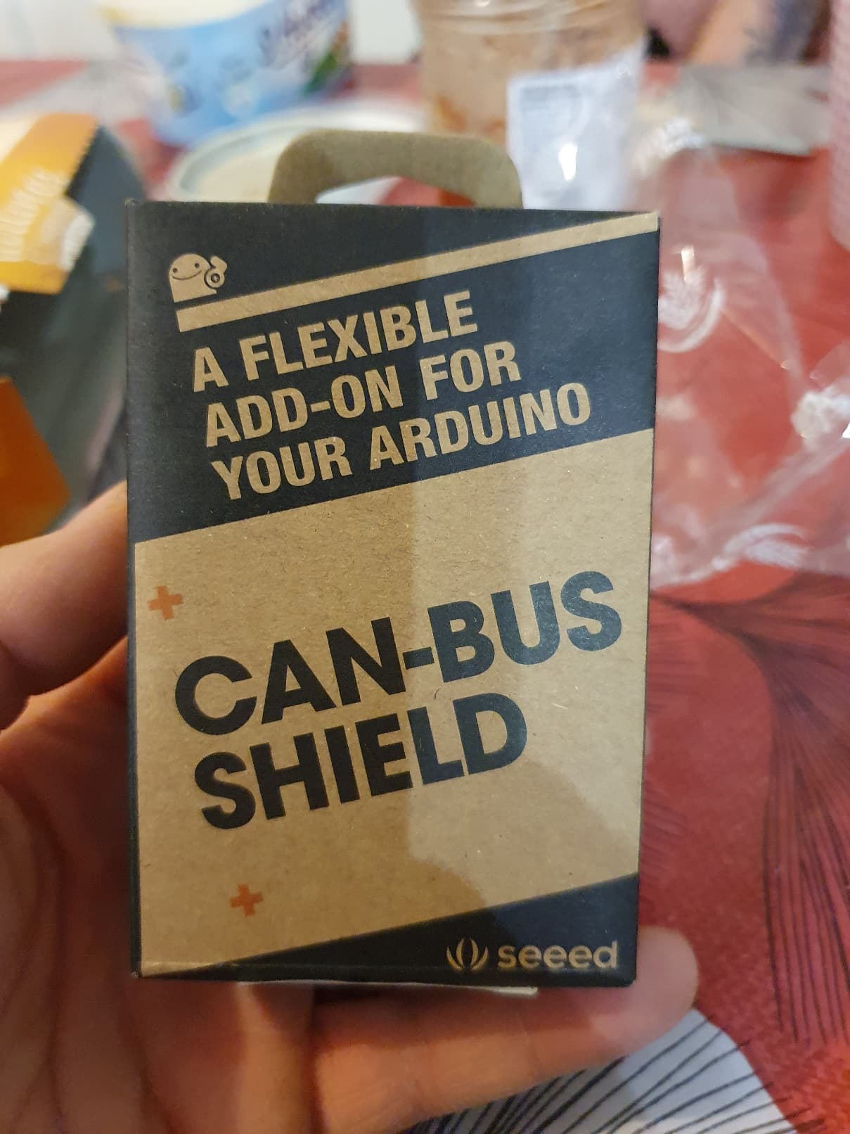
The Can-Shields are almost the same. I work with a cheap one from keyestudio. It worked on the first attempt.
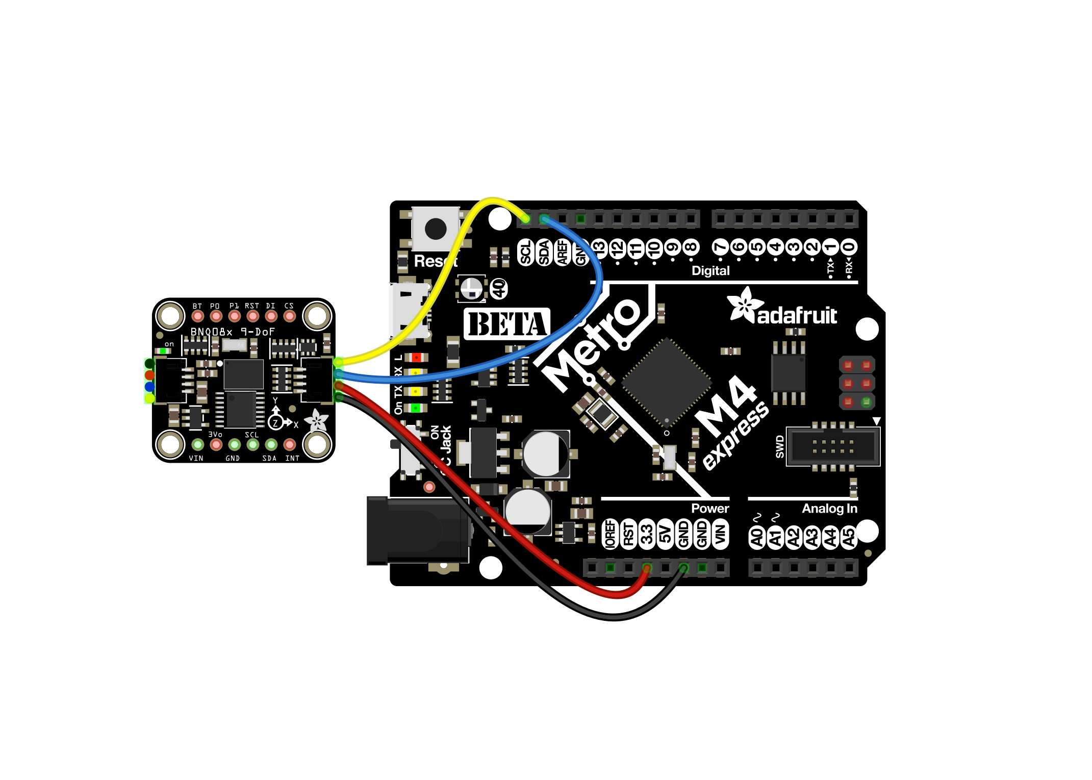
Connecting the BNO085 is really easy. You find a description on the Adafruit website.
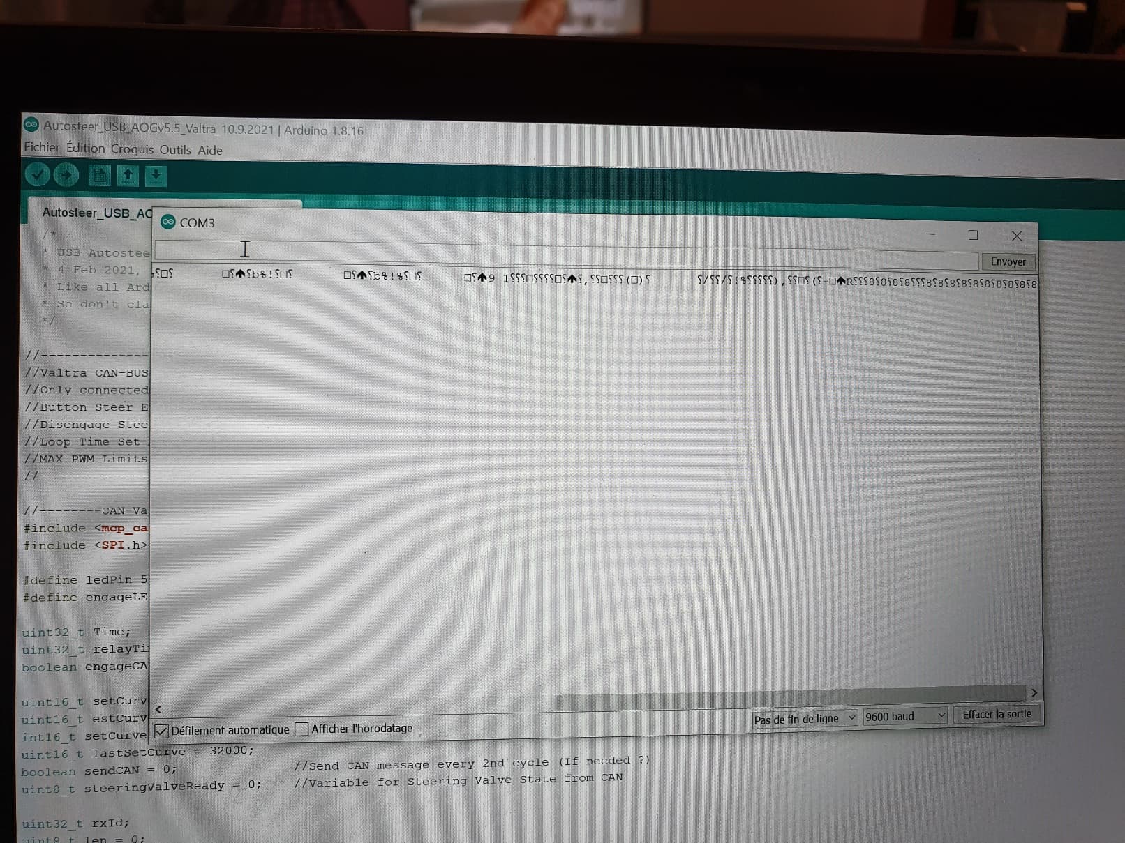
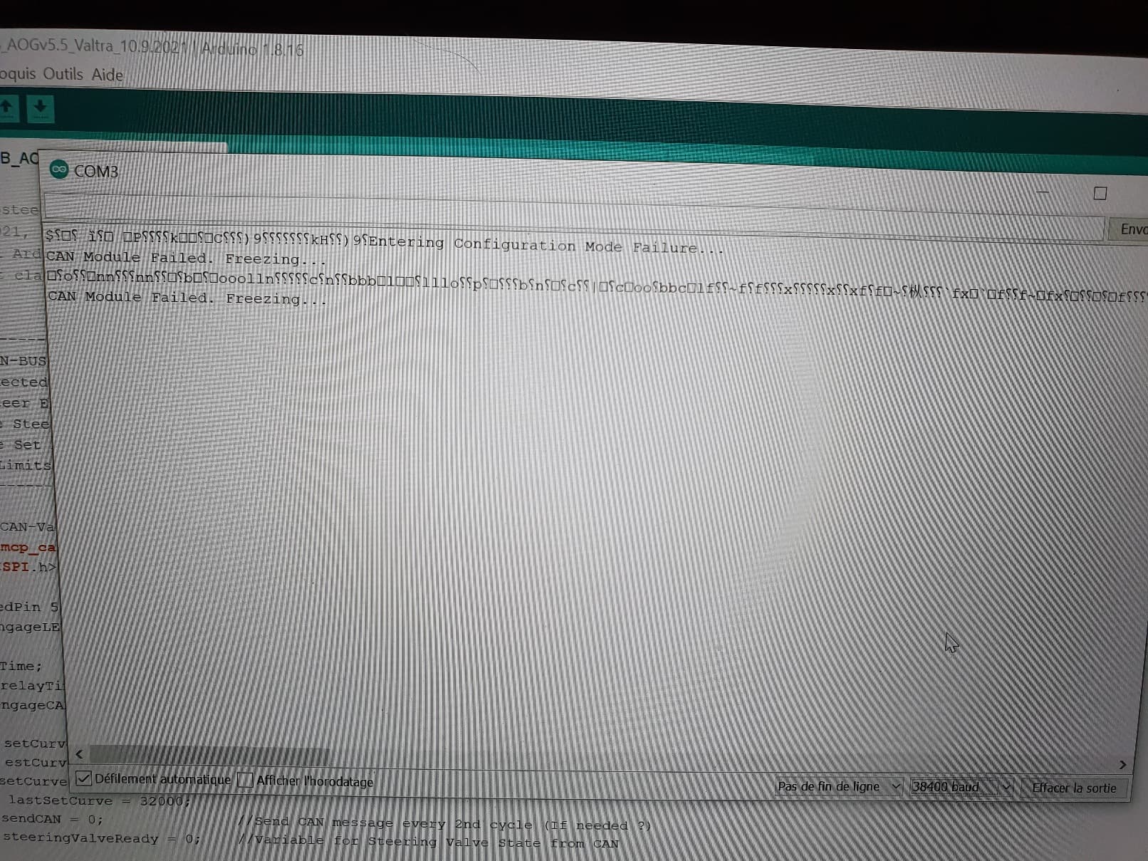
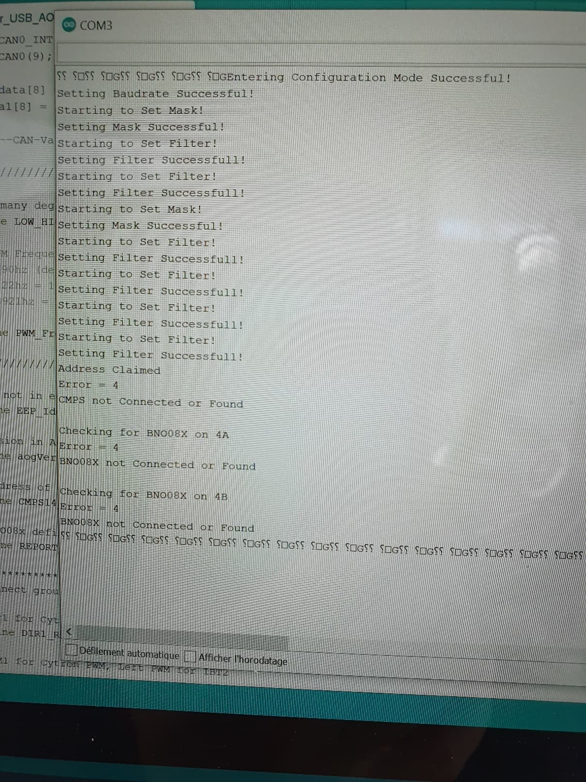
Installing the .ino files on the Arduiuno
First download the files from Github: GitHub - MechanicTony/AOG_CAN_Uno_Nano: AgOpenGPS using Arduino Uno/Nano with CAN Shield
Download the MCP_Can Library: GitHub - coryjfowler/MCP_CAN_lib: MCP_CAN Library
Unzip all files.
Load all the .inos from tony because there are dependencies.
Embed the MCP_Can Library.
Upload the sketches to the Arduino.
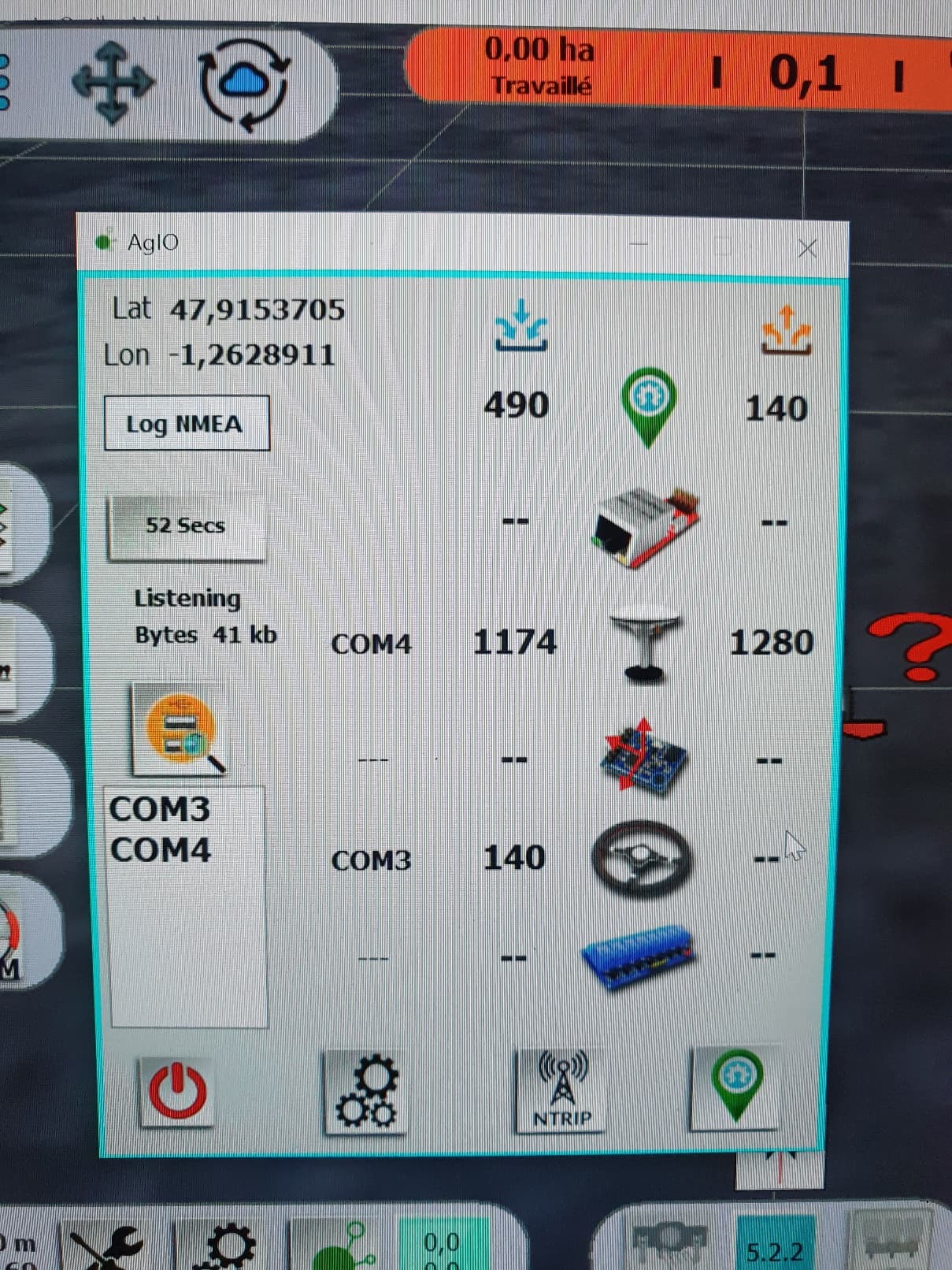
Setting up the Ardusimple RTK2B and the NTRIP client is explained in details on the forum. Please do not forget to configure it as rover as described here:
As I am living in Bavaria, I can use the RTK Correction signal from Sapos Bayern. To connect to the NTRIP caster, I just make a wifi hotspot with my smartphone. In Windows 10 you can set a wifi network as metered connection to prevend it from downloading updates and high connection costs.
Connecting to the Valve Bus of the tractor:
On the right side under the seat there is a cabinet with the main Battery Switch, Diagnostic harnesses and ECUs. In the back of it you should find a lonely connector marked „X230“. It is a Deutsch-DT 3-Pin that looks like the one on the picture.
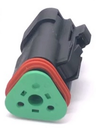
Congratulations! Now connect the green wire to CAN-Low and the yellow one to CAN-High of your arduino shield. „Low = green like the grass, High = yellow like the sun“.
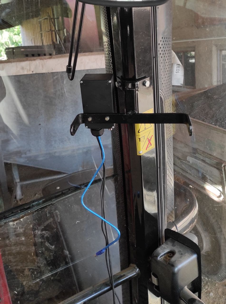
I used standard untwisted unshielded wire. Maybe DMX/Microphone cables from the stage/event equipment are better: twisted and very durable.
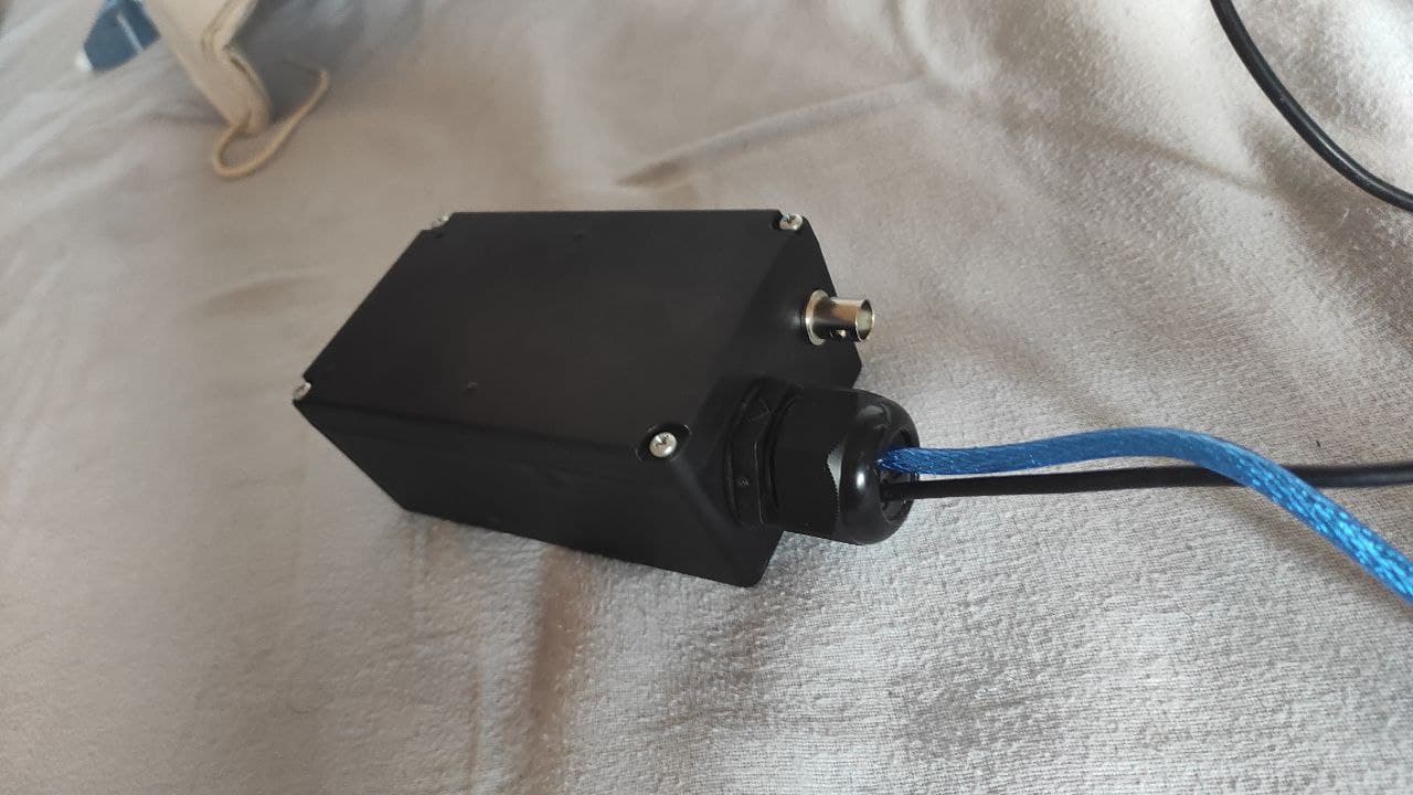
If all works fine, put it in a dust-proof enclosure and mount it in the cab. I do not recommend BNC Connectors for the antenna because they get loose after some time. Go for TNC or SMA instead.
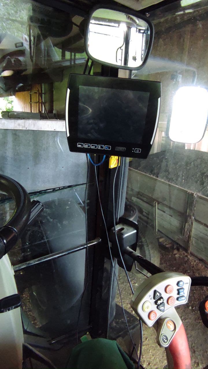
The Terminal is mounted with the screwholes of the original AutoGuide C3000 Terminal. Tablet-PC is powered by the original 12V 3-Pin Front Connector in the right front of the Cab. The tractor kills the power after some time the engine is off so there is no need for a switch to protect the battery.
Basic settings
Most of the vehicle Dimensions are listed in the operator manual of the tractor.
Please do not forget to calibrate the backing up detection:

Steering settings
First, set the correct WAS counts per degree, the steering angle comes somehow not correct from the Can. I set it to 20. The interesting thing is that the tractor does not steer as wide as you can steer manually. This makes U-Turns often very difficult. Maybe someone knows more about it?
My current settings work well but may not be the end of science:
P = 50
Max = 249
Low = 50
Min = 0
Stanley:
aggressivity = 1,3
overshoot compensation = 1
integral = 20
PurePersuit works not as smooth as Stanley in my case.
For engage via button on the tractors joystick and disengage just set “Steer Enable” in the steering settings to “Button” and send + save.
If you have any questions or problems during your build do not hesistate to ask.
Suggestions for improvements are welcome! I am also looking forward to seeing your builds.
Best Regards,
Ferdinand