Hi,
I am a young man in northern Germany, my father owns a small farm, around 60ha, and currently I am a University student. Due to the Covid pandemic I had to stay at home for around a half year now and had a lot time to help my father and think about improvements on our farm. Since I need money for being able to study, I worked on two bigger farms with modern tractors and, who would‘ve guessed, GPS autosteer, Section control and all the other interesting things you can do with modern hardware. I was quite impressed, especially by the first farmer, who even uses Autosteer and Section control on a nearly 30 year old sprayer and tractor, was quite fun to drive that thing. So I thought about what I could do at home to do this, as I believe, important step into the future. About 1.5 years ago I firstly watched Brians early videos and was right away amazed what one guy is able to create is willing to share free with the world. My problem was, I didnt know where to start, and since our farm is really small, even this very small amount of money cant be spend for a project that just perhaps works.
After working again with autosteer this summer I was convinced to give AgOpenGPS a try, encouraged by all success shown here in the forum and on Youtube. Now I only had to convince my father that we really really need autosteer :). Took me about two weeks, then he agreed to install the system on our Claas Ares 816RZ.
Around two months later the bare Autosteer seems to work quite well, due to the lack of a free field I am not able to completely test and set it all up properly, but thats just some fiddling and not a big deal.
In order to help other farmers to do the step into AgOpenGPS I thought about writing a documentation of what I did and the problems I ran into. There are many ways of doing it and mine probably isnt even in the approach of being the best, but might help as a reference for someone.
In the very beginning it is a good start to simply download the latest release of AgOpenGPS from Github:
and install it on your Windows Computer, with no need of an antenna or any other hardware despite the PC. I played around a bit and decided that I need some real hardware to begin with.
For me a good start was to buy the GPS Antenna, since if everything fails, I‘d at least be able to use the antenna as a simple guidance system combined with an already existing windows laptop for fertilizing. My goal was to get an antenna capable of RTK via NTRIP (so via Internet, not as usual via radio signals), thinking the corrections would be free in my part of Germany (which was wrong, but will be soon, hopefully) and that will be used on the tractor (equals used as a rover). So I ordered the widely recommended „Ardusimple simpleRTK2B“ with the „U-blox ZED-F9P“ chipset and the standard antenna directly off the Ardusimple shop:
After a couple of days the antenna and board arrived and I hooked it to my Laptop. For the basic settings of the board I basically followed Aortners instructions here:
, but I ran in some problems with it. To get the latest firmware and config, I used the first link of the post to download U-center. As for the firmware and config, I used the following:
Firmware: https://www.u-blox.com/en/ubx-viewer/view/UBX_F9_100_HPG_113_ZED_F9P.7e6e899c5597acddf2f5f2f70fdf5fbe.bin?url=https%3A%2F%2Fwww.u-blox.com%2Fsites%2Fdefault%2Ffiles%2FUBX_F9_100_HPG_113_ZED_F9P.7e6e899c5597acddf2f5f2f70fdf5fbe.bin
Config for rover: https://discourse.agopengps.com/uploads/short-url/okXH1rULMMvjSax3BloFarPyIa6.txt
I did the firmware update as explained, but since U-center updated, to apply the configuration, I had to click Tools - „Reciever Configuration“ instead of „GNNS Configuration“, then select the configuration file and upload it to the simpleRTK2B. In order to save the configuration, I clicked View – Messages View, went through the directories ubx>cfg>cfg and clicked send. I had to do this a couple of times, because I didnt find the option to save the settings. Later on I had some problems getting RTK fix, so I tried different configs, but in the end the latest config from Aortner works perfectly, that was not the fault.
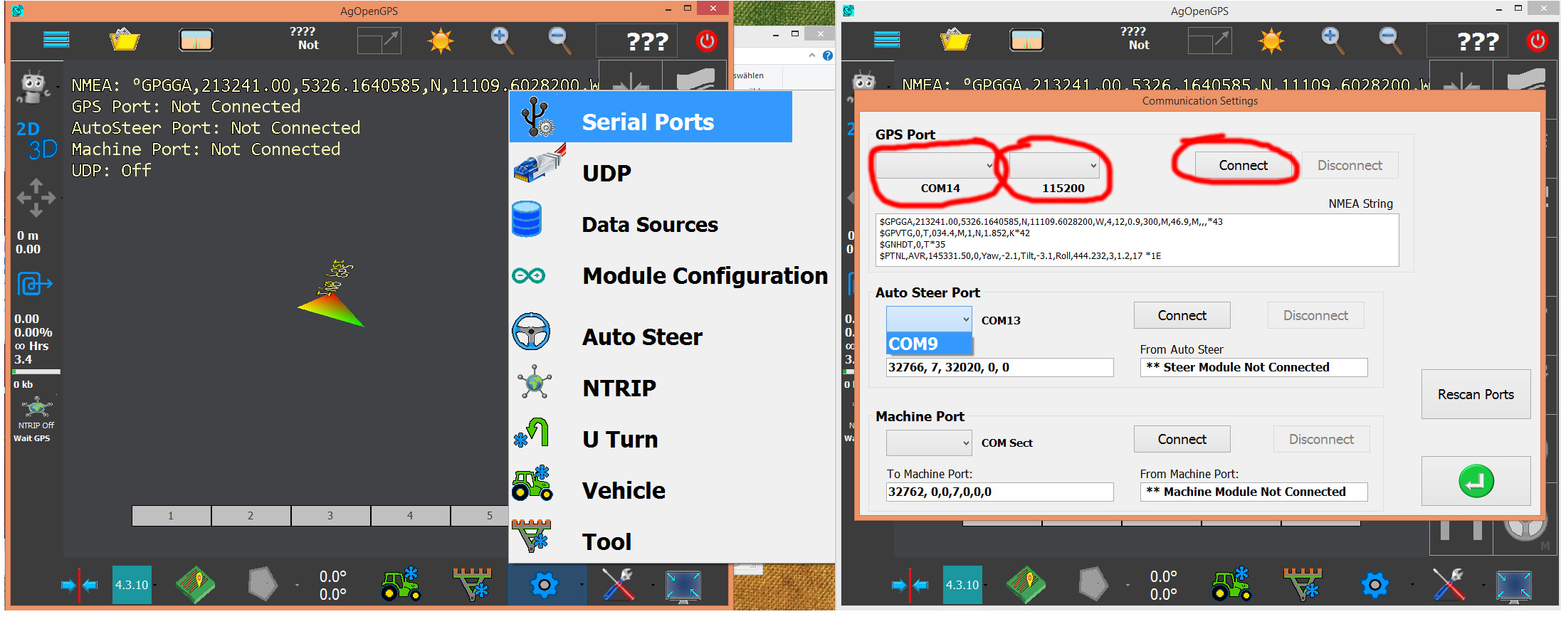
To connect the antenna to AgOpenGPS, I did the following:
When I found out that in wont get free RTK in my area (SEE UPDATE MARCH 2022), I had to find another solution, because building my own base was (and until now is) no option since I wanted to keep cost as low as possible. So I went to www.rtk2go.com and found a caster (equals RTK-base) thats around 40km away from me, which isnt perfect, but should work ok. But it didnt…
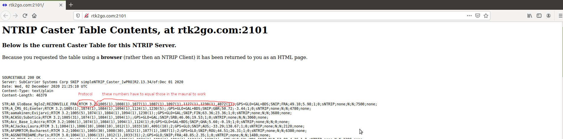
To find a caster I simply browsed the caster table here:
http://rtk2go.com:2101/
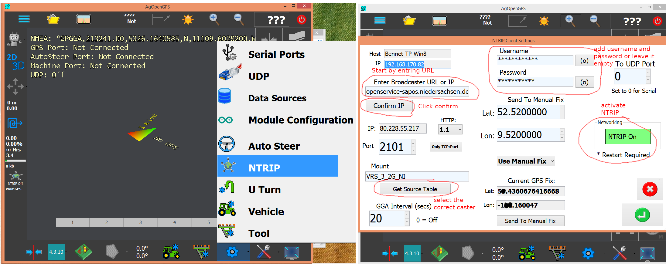
and found one, but AgOpenGPS also directly shows the caster with the lowest distance to your position after I entered the link above in the NTRIP Settings in AgOpenGPS.
In order to test if everything works, I simply used AgOpenGPS, but for debugging U-Center is much more useful and not really more complicated. To enter the settings I did the following:
Also it is important to set the NMEA rate to 10Hz with this configuration:

I was never able to get a RTK fix (in my understanding the best possible accuracy) but mainly Float (second best accuracy) or even DGPS (even worse). Problem was that the caster didnt send the right data. At first I only looked at the protocol version of the caster, in this case rtcm 3.3, what is readeable by the simpleRTK2B. But the data stream is partially not understandable for the simpleRTK2, so in fact i didnt have RTK at all, because the „Message Type“ was not compatible. Compatible messages can be found in the manual of the Chip „ZED-F9P“ and messages send by the caster are shown in the caster table.
My third and last solution without an own base was to use free RTK from another part of Germany. I registered and entered IP, username and password as shown before in AgOpenGPS, selected the correct caster and now it worked just great, even with a base around 200km away from me I get a stable RTK fix. I cant tell how accurate it really is since I had no opportunity to properly test my system in the field, but the Ardusimple support told me that the pass to pass accuracy should be decent.
So I passed the first important step and got the antenna working good.
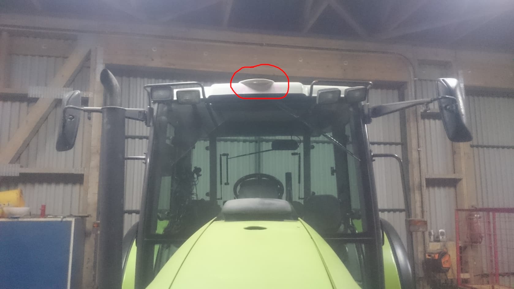
Here is my final install of the antenna on the roof of the cabin:
Now I went on and thought about how to build the rest of the system.
Next step for me was to understand the correct wiring and setup to control my steering motor. I went through some instructions here in the forum, but I think its easier to just order a pcb and solder everything together. I got my pcb from JLCPCB quick and relatively cheap and, at least from what I can tell, in good quality. To order the pcb, I downloaded the Support Files from GitHub: Releases · farmerbriantee/AgOpenGPS · GitHub. Then I went to https://jlcpcb.com/, clicked „Quote Now“ and on the next page „Add your gerber file“. I selected Support_Files/PCB/AutoSteerPCB_Gerber/GerberFiled.zip from my harddrive and didnt change any setting on the website, I just placed the order. Done.
To order the components for the PCB I went to Mouser Electronics and searched for all the parts mentioned in Support_Files/PCB/AutoSteerPCB_Gerber/PartsList.xlsx manually because I had some of them already at home. I refered to the specific part numbers to really get the right parts. As I found out, some parts are not nessesary. Especially I didnt need three relays, only one: 255-1832-ND seems not be used. For using a electric motor to actually control the steering wheel, I didnt need a proximity switch and since I use standard USB connection and no UDP to connect to the pcb I didnt buy the Ethernet Module.
I would like to add some connectors to the list, two times „A98333-ND“ and one extra A98334-ND to be able to screw the cables of the power switch instead of soldering them and also extra connectors to grab 5V and 12V.
PartsList.xlsx (10,4 KB)
To solder the pcb I followed the following videos: https://www.youtube.com/watch?v=BXys4PYzAFQ and https://www.youtube.com/watch?v=qZR5NlGGiSo
It was quite helpful to watch them before ordering the parts so I at least kind of knew what I have to do.
THE FOLLOWING REFERS TO V4.1.3, NOT v5
After the soldering was done, I felt ready for a first test. The first thing to do is to upload the code to the arduino with the Arduino IDE. I installed it and loaded Support_Files/ArduinoCode/Autosteer_USB_4.3.10/Autosteer_USB_4.3.10.ino into the program. I didnt edit anything, I simply uploaded it to the Arduino. Only issue with that was that my Arduino Nano uses an older Bootloader that had to be selected in the Arduino IDE. Then I hooked a power supply and a simple potentiometer (as a wheel angle sensor) to the pcb (+5V and ground connected as stated on the pcb, the signal wire goes to „High“) and connected a motor to the motor driver.
After that I fired up AgOpenGPS, selected the correct port here

and played around with AgOpenGPS a bit until my motor spun, slowed down when turning the potentiometer (so the simulated wheels) to zero degrees and basically did what it should. Helpful video about that: https://www.youtube.com/watch?v=XNqwzcfyq-8
In general Brians videos were very helpful to understand what I was doing, and still are: https://www.youtube.com/user/FarmerBrianTee/videos
Now I was ready to start thinking about how to adapt a motor to my steering wheel. I also still thought about what motor I should use, but I ended up with the widely recommended Pidgets Motor described in the parts list.
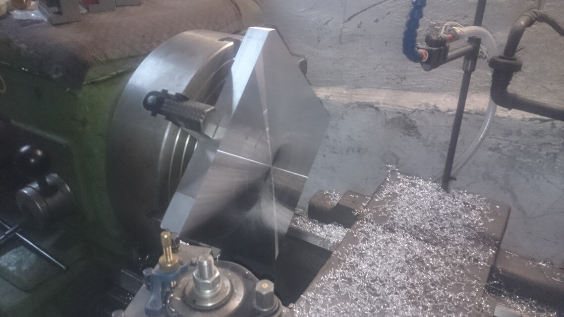
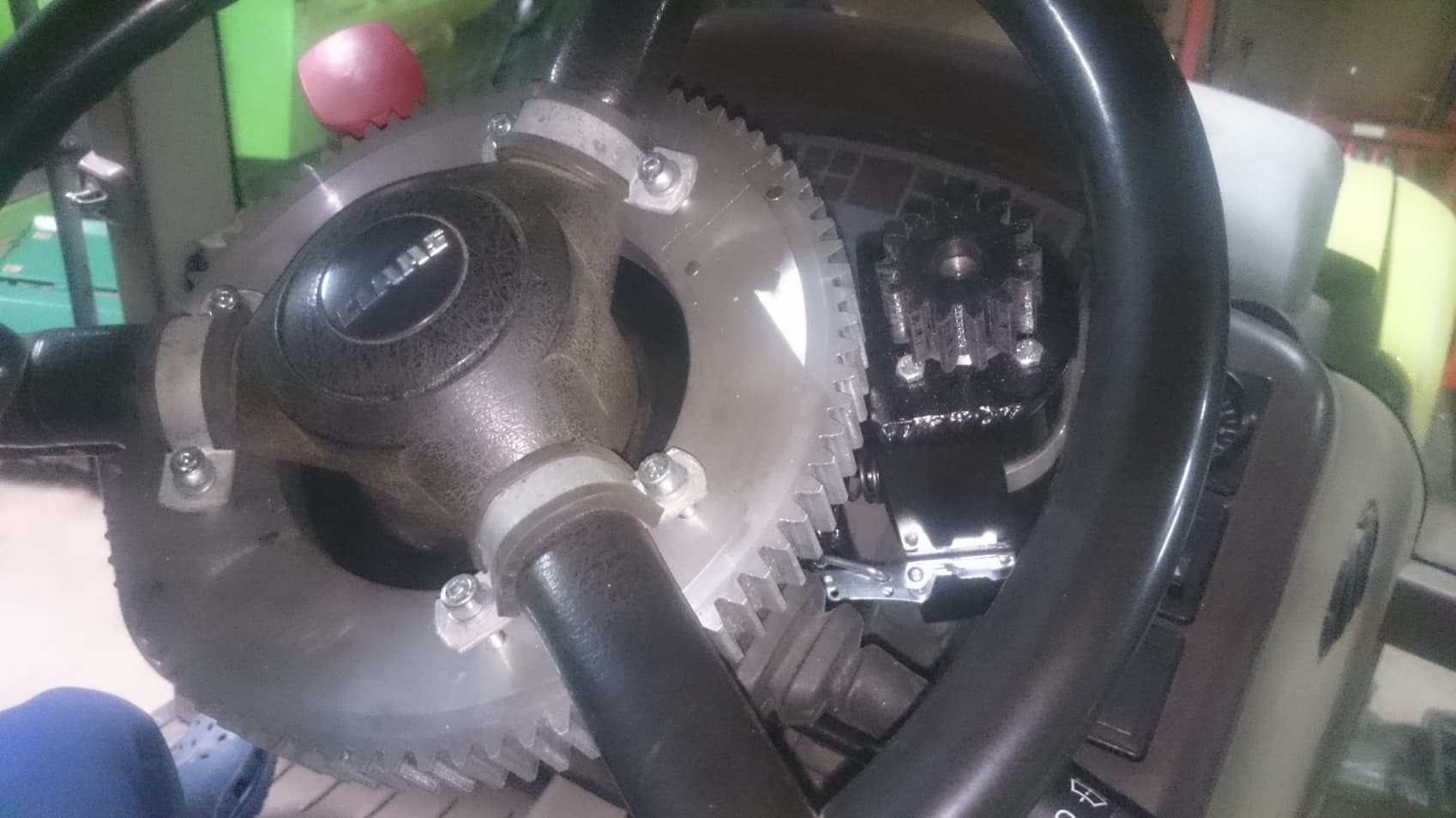
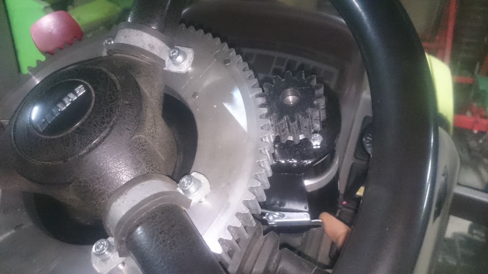
I wanted something robust but still as subtle as possible. In spring I bought a new mill with a lot accessory to it and to give it a first real project instead of just playing around I decided to mill a gear out of aluminum that got mounted to the steering wheel.

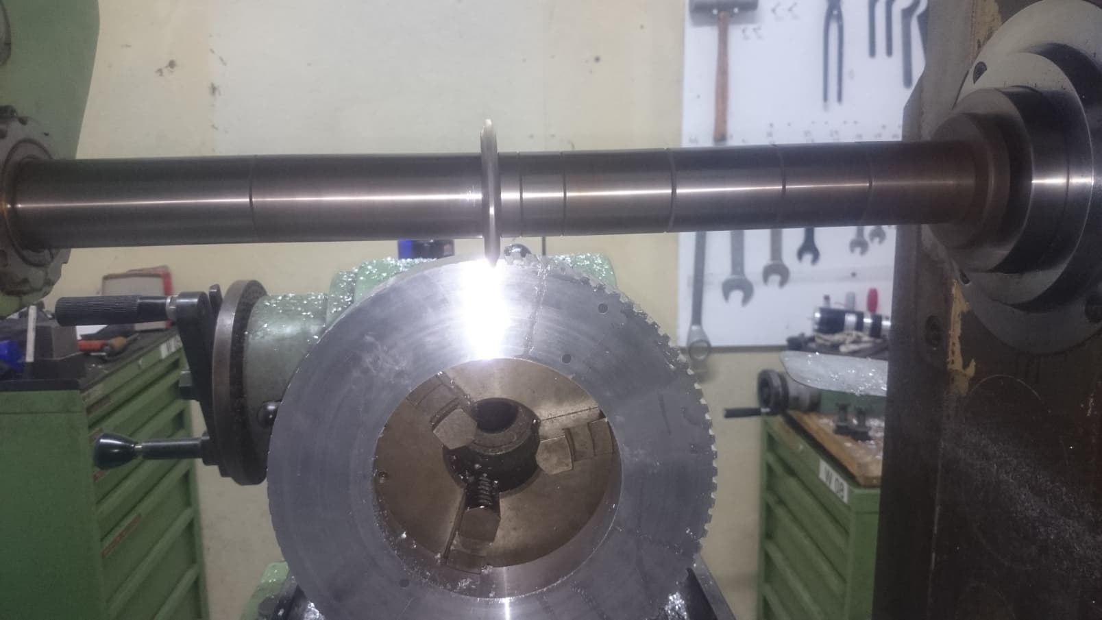
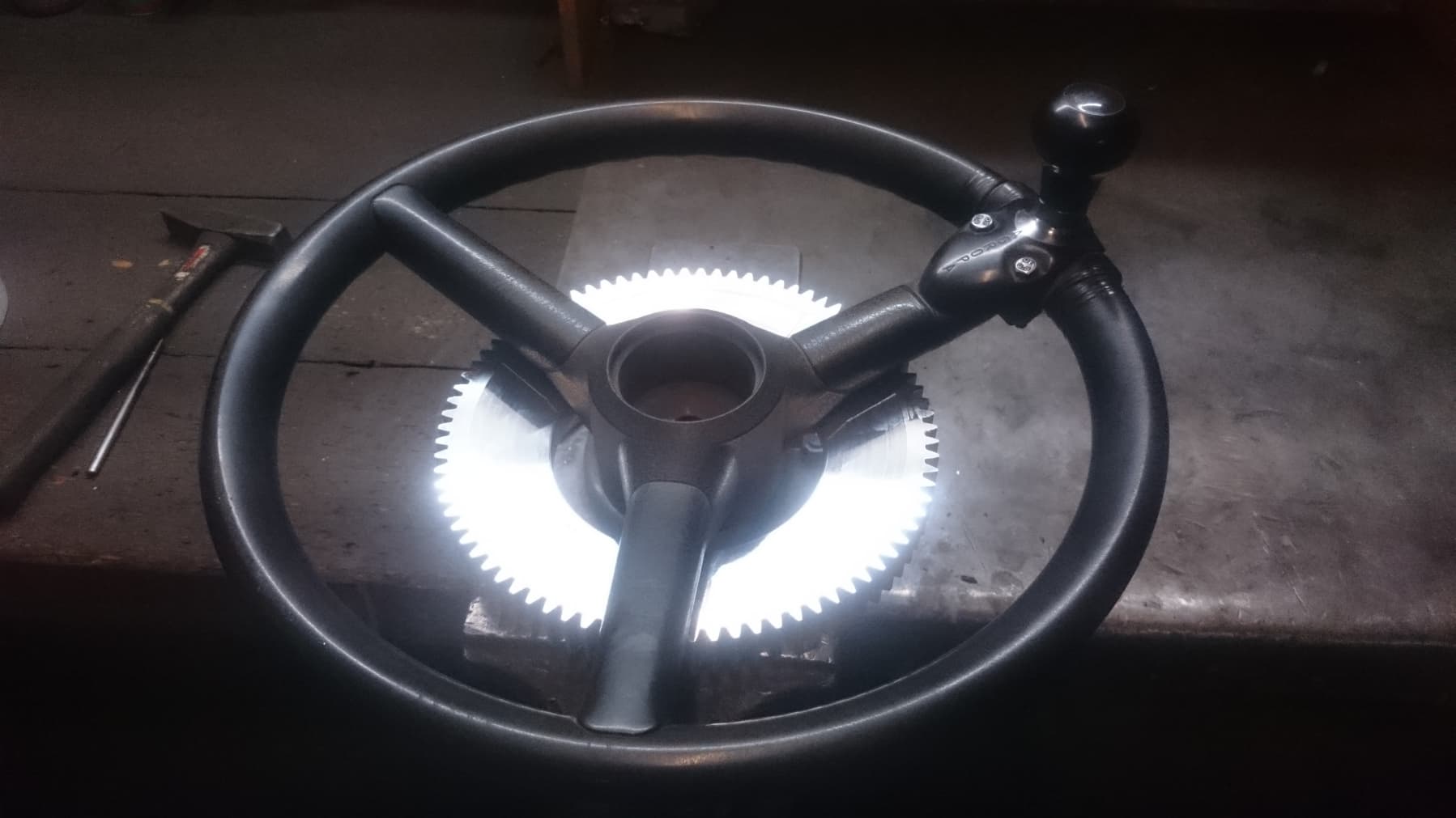
The other gear mounted onto the motor shaft was printed, I hope it will be a lot more quiet than two metal gears and its easy to replace if it fails. Because the steering column is quite large on this tractor, I had to make the gear bigger than I wanted to. Problem with that is that with the motor engaged but turned off its still relatively hard to turn the steering wheel by hand. Maybe I will change that in the future, but for now its has to work.
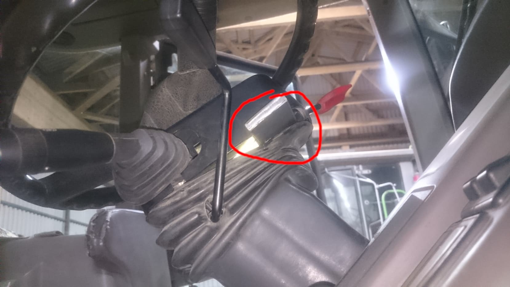
To mount the motor to the steering column I disassembled it and attached a piece of flat bar with two tapped holes in it to to the column:
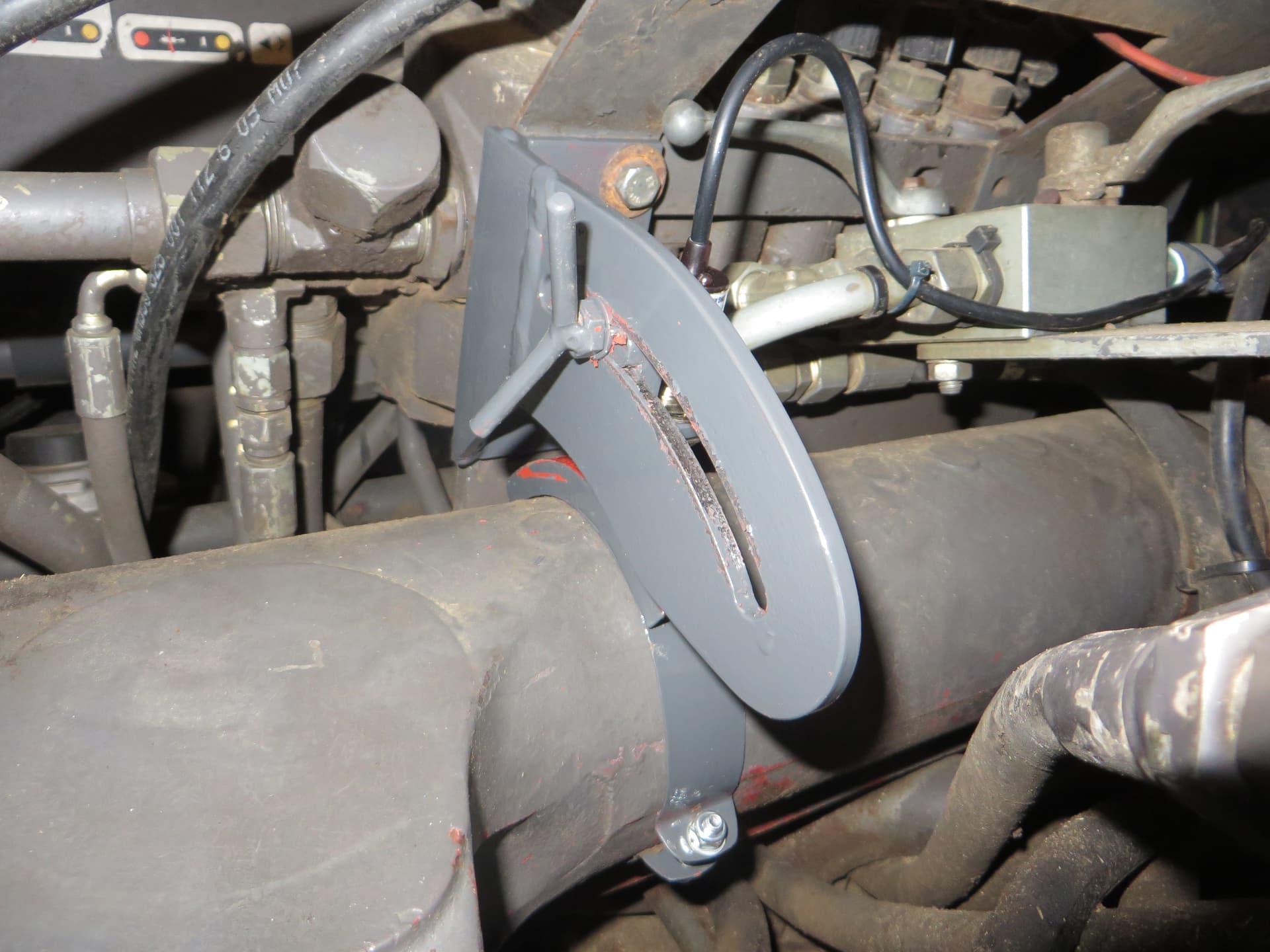
After I mounted the big aluminum gear, I started to measure the distance the motor would need relative to the flat bar. I created this mechanism, based on some videos I found on YouTube:
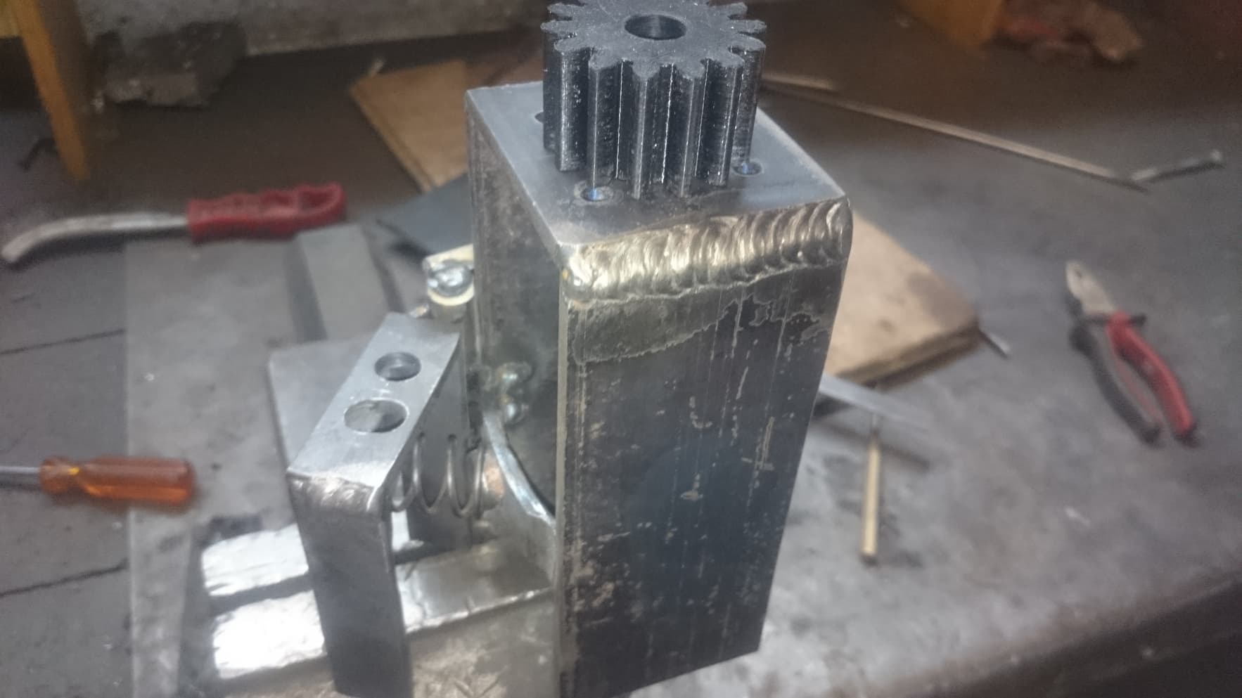
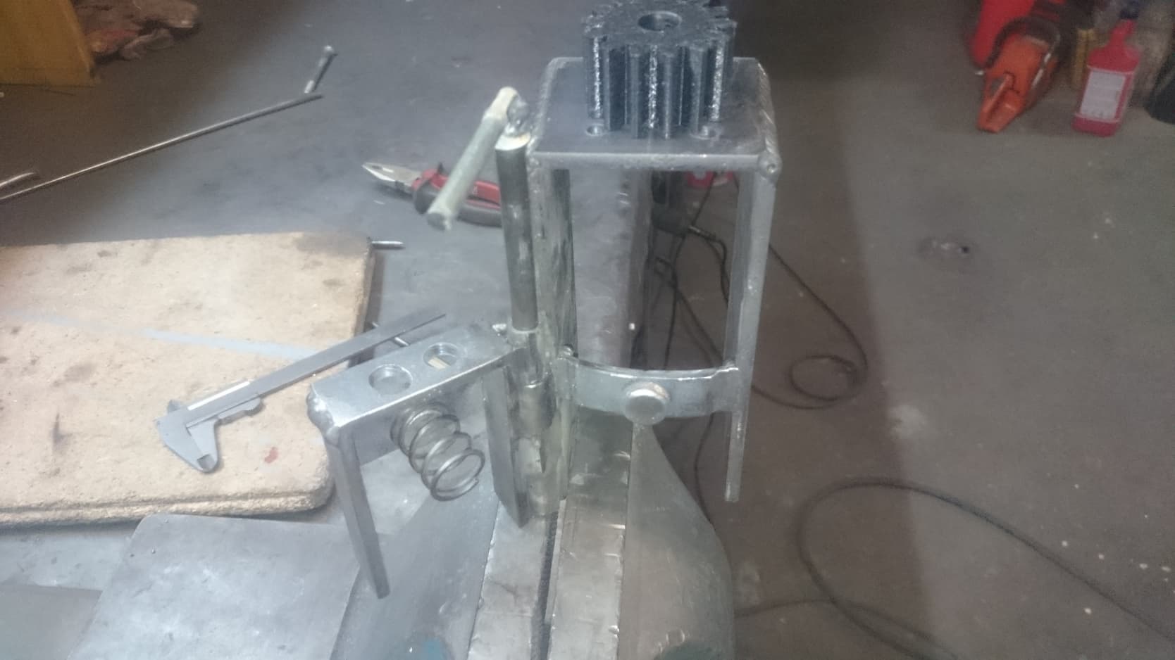
With that I can easily attach and deattach the motor to the steering wheel with one hand. I made it spring loaded so the motor cant get in touch with the steering wheel while disengaged. Turned out great, Im happy with the handling till now.
WHEEL ANGLE SENSOR DESIGN CHANGED, SEE UPDATE MAY 2021
The last really important step is to mount a wheel angle sensor. My tractor has a suspended front axle and automatically disengages the differential lock at a certain wheel angle. So I thought I can use the existing sensor, but again I was wrong.
As already stated in another post here in the forum ( Steering wheel deadband - #5 by Larsvest ), there is a control pin that connects the sensor to the king pin in the axle and that was worn out.
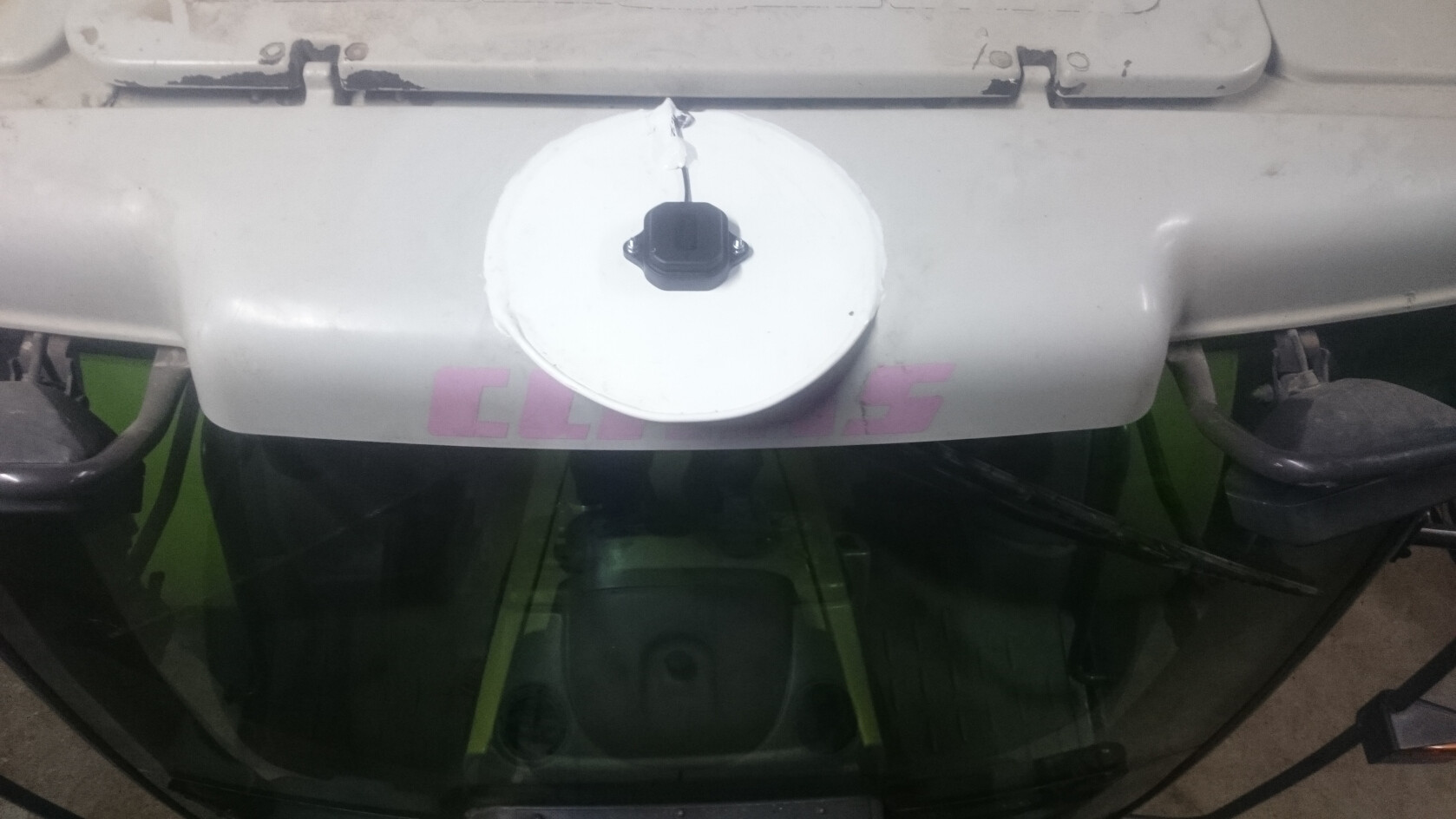
The sensor is placed under this casing on the left side of the tractor, unfortunately I have no image of the sensor itself in place…

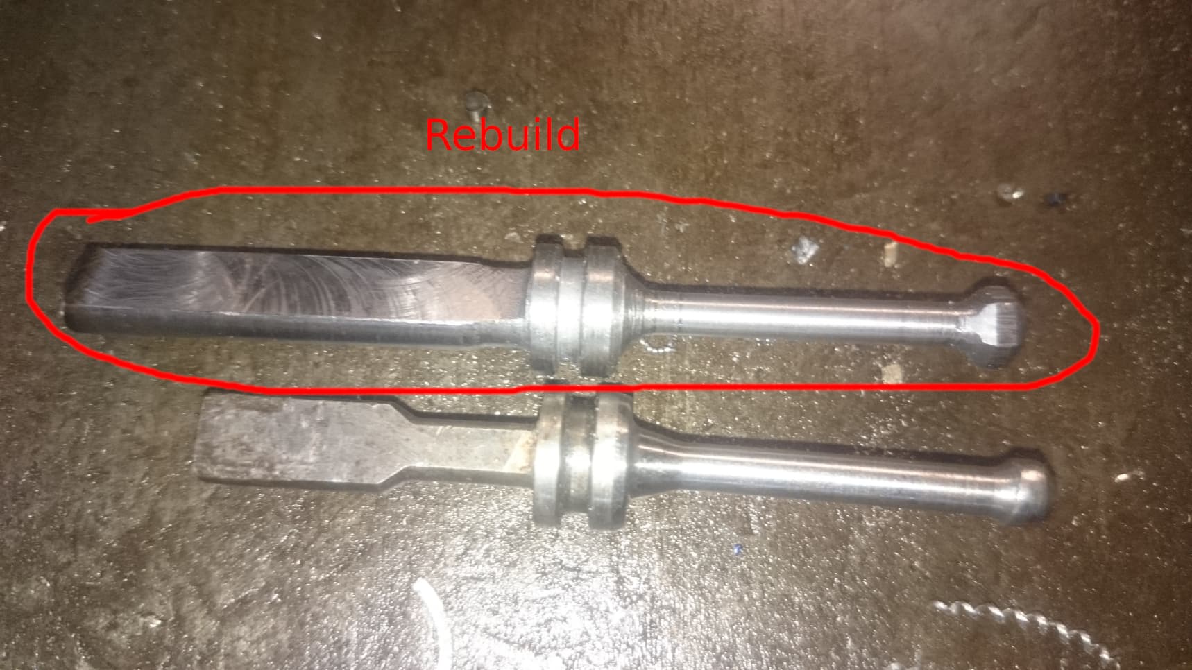
I turned and milled a new one, in the picture placed next to the old one. But after a bit of troubleshooting I realized the sensor itself was broken too. I contacted the user Baraki, he really helped me out. He told me to buy a hall sensor rather than a potentiometer because its more stable and precise. So I bought this sensor: https://www.digikey.pl/product-detail/pl/amphenol-piher-sensing-systems/PST360G2G2-1A-C0007-ERA180-05K/1993-1013-ND/9555851
The tractor ECU does not supply enough power to power the sensor, so I had to use power from the PCB. I wanted to share the signal between the tractor and AgOpenGPS, but that just caused a lot of trouble. I simply bought the factory sensor and installed it above the hall sensor, so every system has its own sensor (in fact I bought this sensor, which is the same as the factory one, but around 120€ cheaper, completely ridiculous: https://www.ebay.de/itm/DROSSELKLAPPE-SAUGROHR-DROSSELKLAPPENSENSOR-DROSSELKLAPPEN-POTI-POTENTIOMETER-/391142845441 ). For reference, the OEM number is CARRARO 131897.
Since the hall sensor has a through hole, I simply put the factory ontop of it, connected with a printed adapter. I ran a cable in the cabin and the wheel angle sensor was successfully installed.
Now the tricky parts were done.
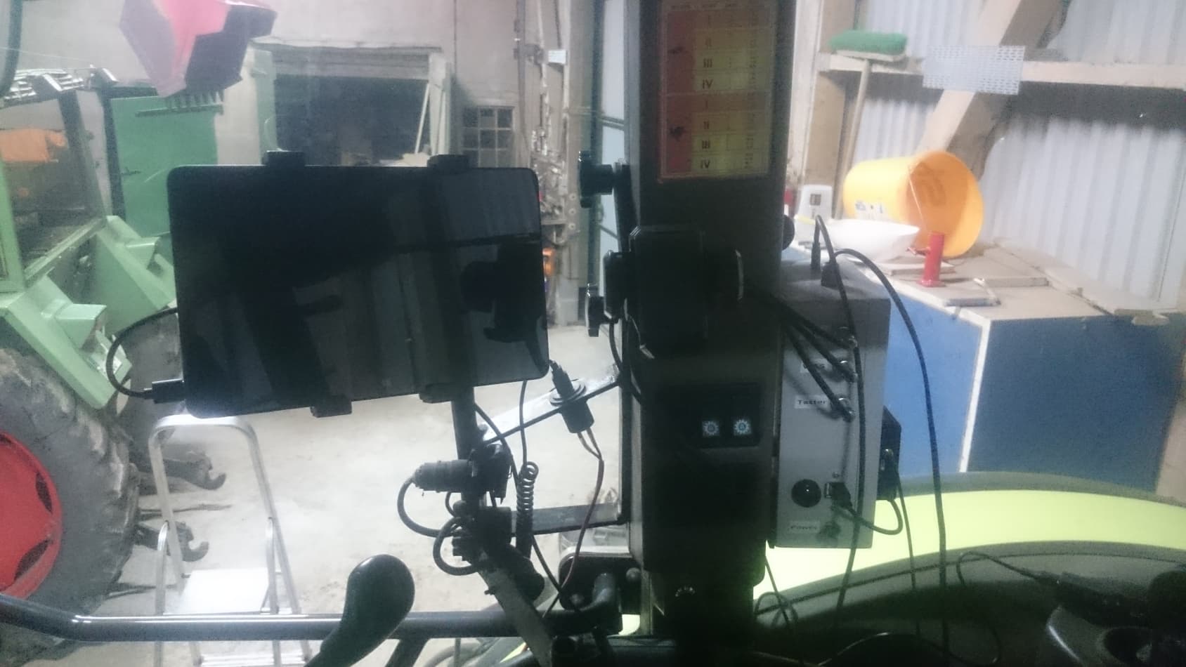
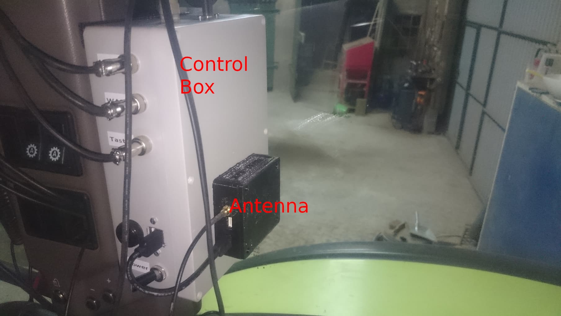
Parallel to the setup on the tractor I wired up the control box with the pcb. I ended up with that:
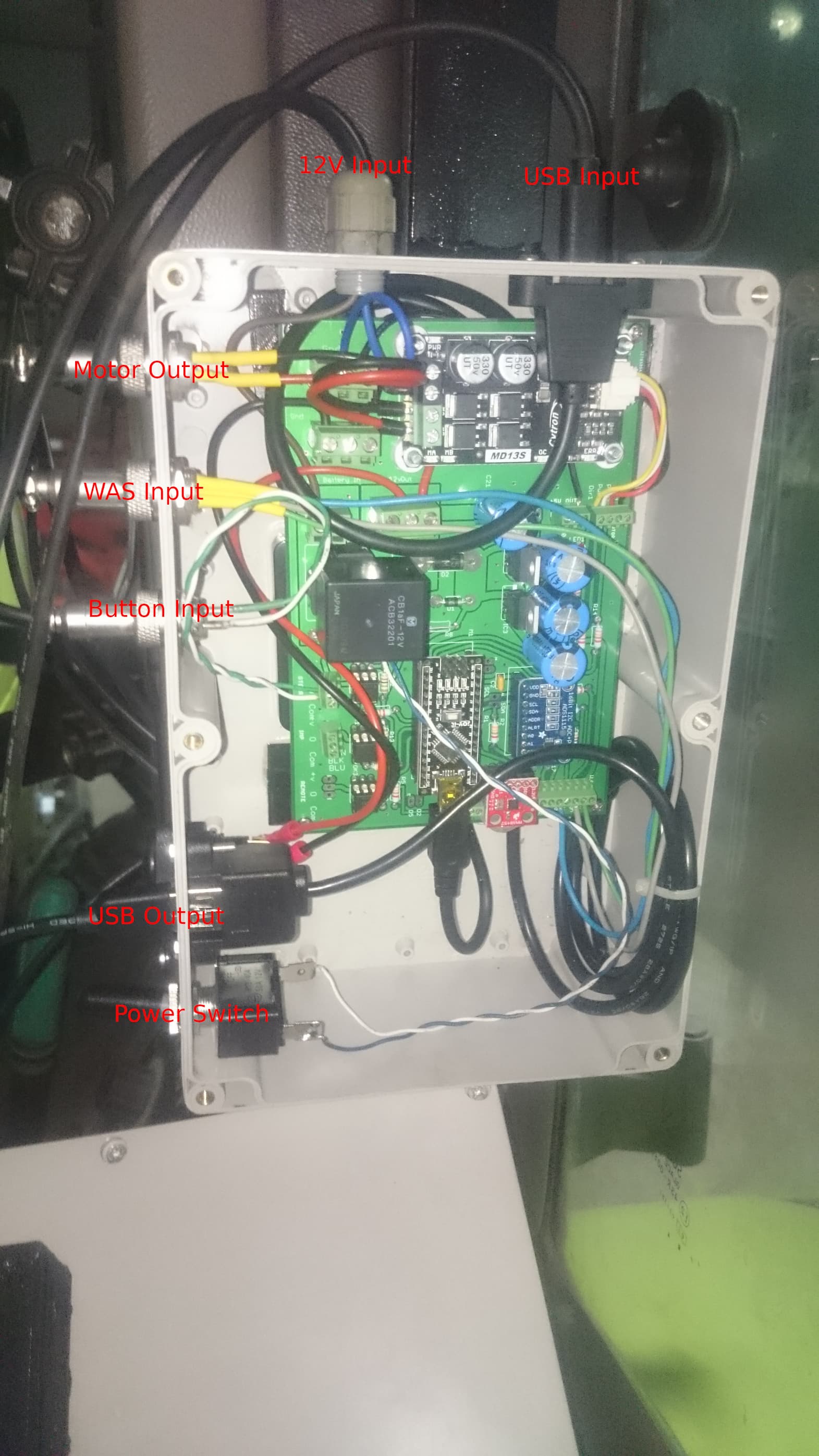
Could be better, but should do it. I connected everything to a powered USB hub that connects to my tablet that I bought at that time too, together with a holder for it. I decided to use the Dell Venue 11 pro, which I got off Ebay, together with the holder and the recommended mobile power supply ( https://www.ebay.ca/itm/324104743460 ). I just installed AgOpenGPS on it like on a PC, nothing special done to the tablet. To get internet access, I found a free solution provided by „Netzclub“, they offer 200mb free high speed data per month in Germany, that should hopefully be enough.
Now I got ready for a first real world test: First thing to do is to adjust the wheel angle sensor. I had to change the value in the Arduino code a little bit to be able to get AgOpenGPS to find the real zero point. A good way to configure autosteer is described here (it done with an older version of AgOpenGPS, but its basically still the same) :https://www.youtube.com/watch?v=CB1Zj8KjcSY
I personally just played around with these settings until I was happy with the result, but I will definitely have to do some more adjustment next summer on the field.
Some issues I had while setting up:
- Single vs Differential mode for the WAS:
- if you use an extra sensor just for AgOpenGPS, you use Single Mode and the pins mentioned before to connect. I tried using Differential Mode, but got just bad results with my hardware, so I went back to Single
- I installed the WAS directly at the „turn point“ of the wheel, so I have to keep Ackerman steering in mind, especially for U-Turns:
- what is really important: after changing anything in the Arduino code and uploading it again, you always have to send your module configuration again, otherwise the Arduino will ignore it

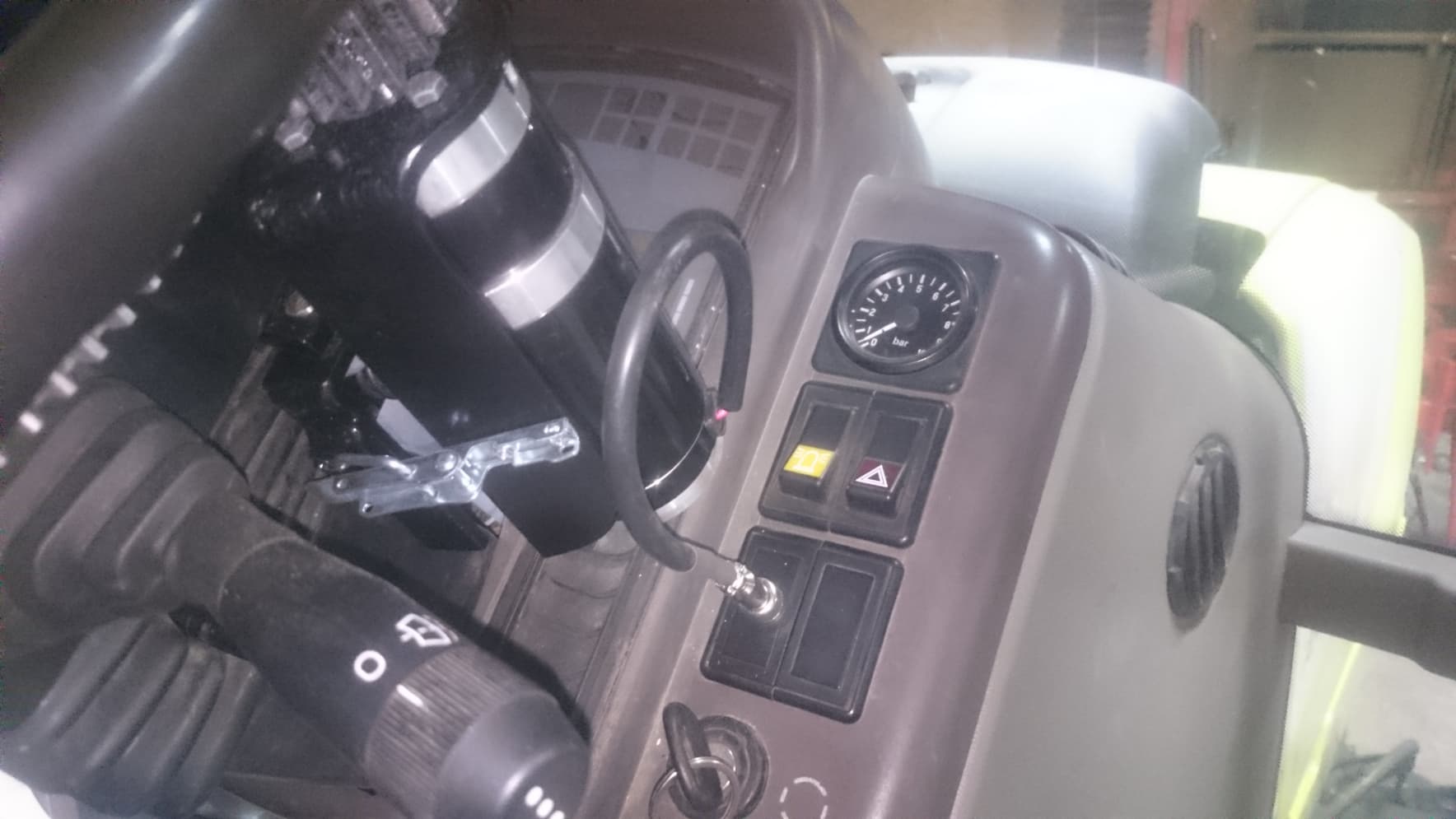
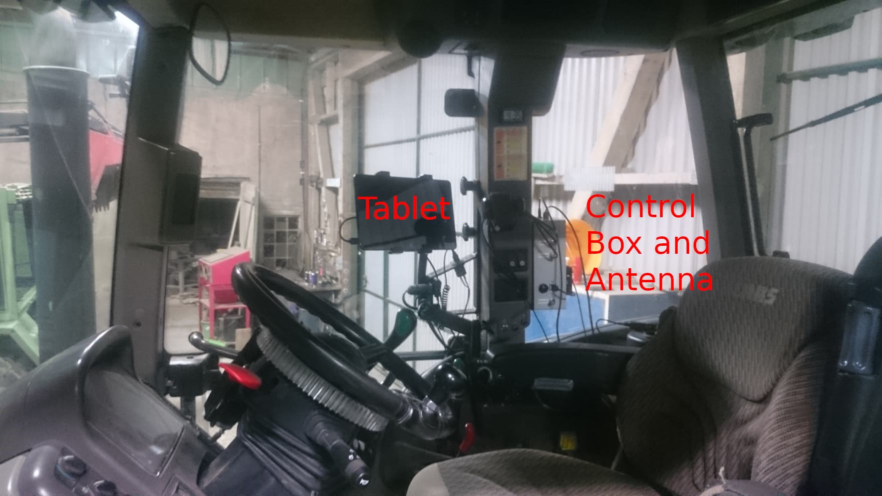
Machine control like automatic hydraulic lifting is in my mind, but I have encountered some problems with how my tractor controlls it. Section control for a sprayer will probably done in the future, but for now I want to test and use autosteer. Here is my setup in the cabin so far:
Now a few things I noticed that I dont like about my setup: The aluminum gear is a bit too large, this interfears with the display for engine rmp and speed of the tractor. Also the gear ratio to the steering motor is bad, so turning the steering wheel by hand while motor is engaged is not comfortable (SIMPLY BECAUSE THE CYTRON WAS BRAKING THE MOTOR, SEE UPDATE MAY 2021, RELAY TO PWM2). The cable management is not perfect at the moment, I might have to improve it a bit. But there is plenty of time for that.
I guess I forgot to mention a lot, but maybe this here helps someone out who just as me has no real clue about coding and electronics. Thanks to the community to share their knowledge and help me out with some issues, and to Brian who makes it possible to use his great software.
Greetings
Bennet
Update May 2021
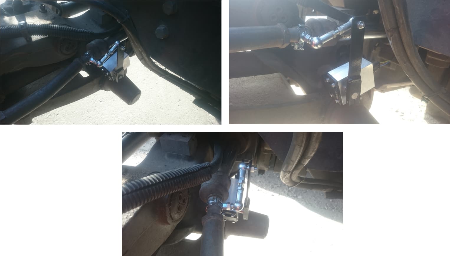
I had to completely rebuild the WAS mount, because the new pin I milled got used up extremely quick and so had backlash. I build this based on some drawings directly from Claas:
I also added a relay switched by PWM2 that breaks the circuit between cytron and the motor to make turning the steering wheel by hand easier. After updating to v5 I also connected a current sensor (ADS712) to A0 of the arduino so that AOG can disable autosteer when a current limit is exceeded, so when I try to turn the steering wheel by hand. It measures the current of the supply voltage for the cytron.
I now use a step up module so the motor runs on 24V now instead of 12V. Was really worth it, the Phidgets now turns a lot faster and has plenty of power.
A real big problem I had was that my USB connection was basically not useable while the tablet got charged. That problem was caused by not using single point grounding. After I bought a 12V socket for my charger that was connected to the ground of the PCB these problems were gone, so far the connection is very stable.
I finally implemented machine control, works great, also with v5. The last thing I did was to add the CMPS14 in a seperate box with an extra Arduino. It seems like it makes the steering even better than with single antenna only.
Update March 2022:
After one year of use I have some things to say: First of all, I needed to print a new plastic gear for the motor, the original one lost some teeth due to extreme movements of the motor while I tried to reset my IMU with autosteer enabled.
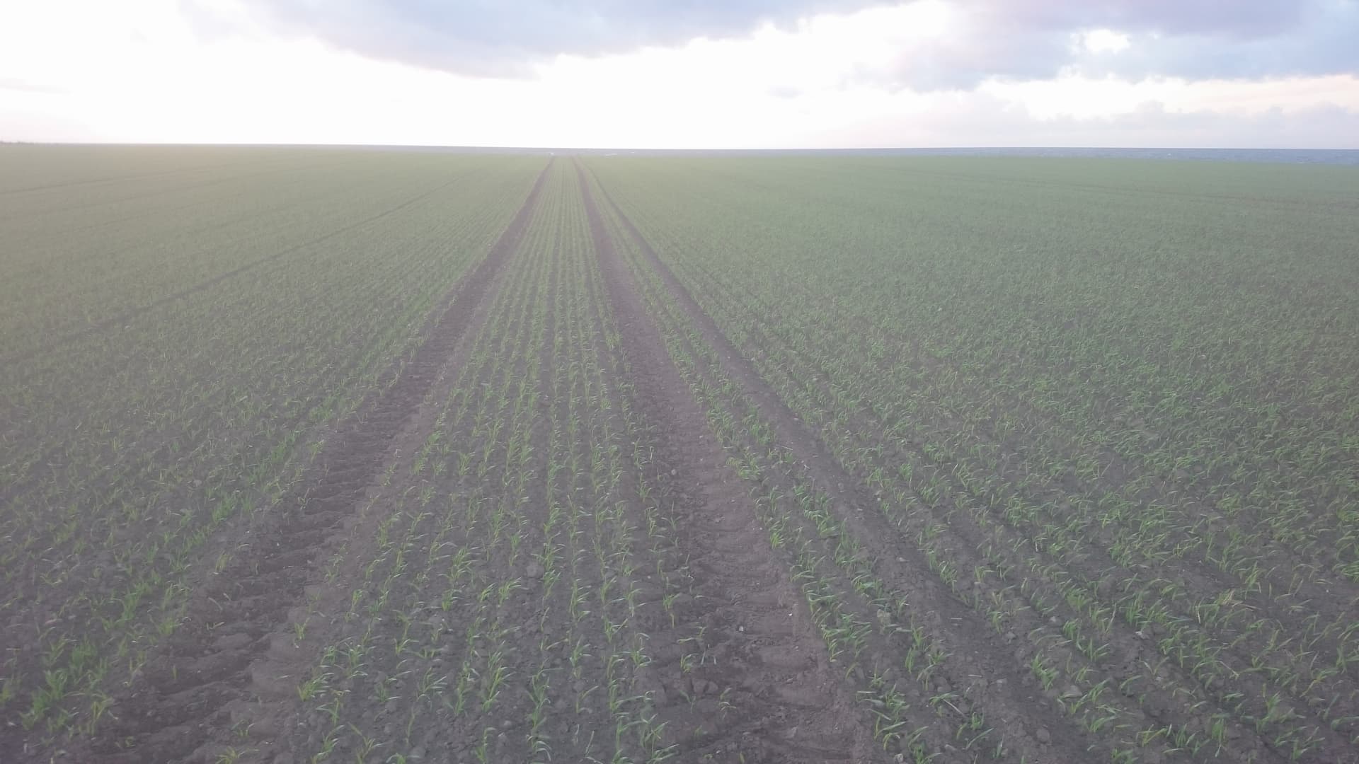
Second thing: The hood of the cabin probably isnt the best spot for the GPS antenna, at leat for single antenna. It seems like my suspended cabin is moving too much. Moved it to the engine hood but did no testing till now, hopefully it will get better like this.
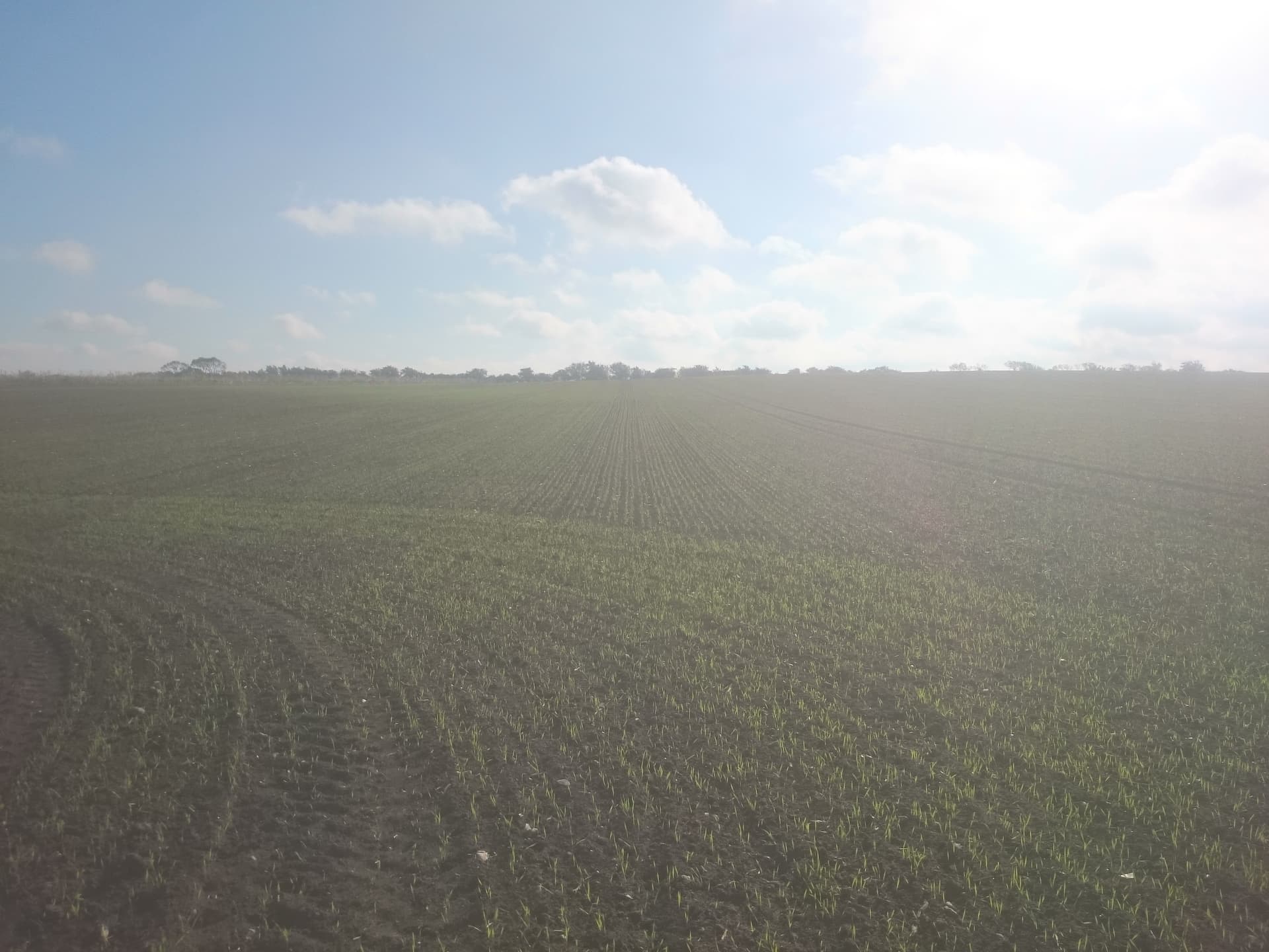
This is how my seeding went last autumn with the antenna still ontop of the cabin (zoom in to see the rows, my camera is not the best…):

I also got rid of the additional arduino for the IMU and bought two of those: Qwiic Differential I2C Bus Extender (PCA9615) Hookup Guide - SparkFun Learn
hooked one directly to the pcb, network cable in between and the IMU wired to the second i2c extender. This way there is no need for an additional module that has to be connected individually.
Last summer I paid for a RTK licence, but this post https://discourse.agopengps.com/t/openly-available-rtk-correction-signals-in-europe/7961 looks very promising to me, will try it out this year!
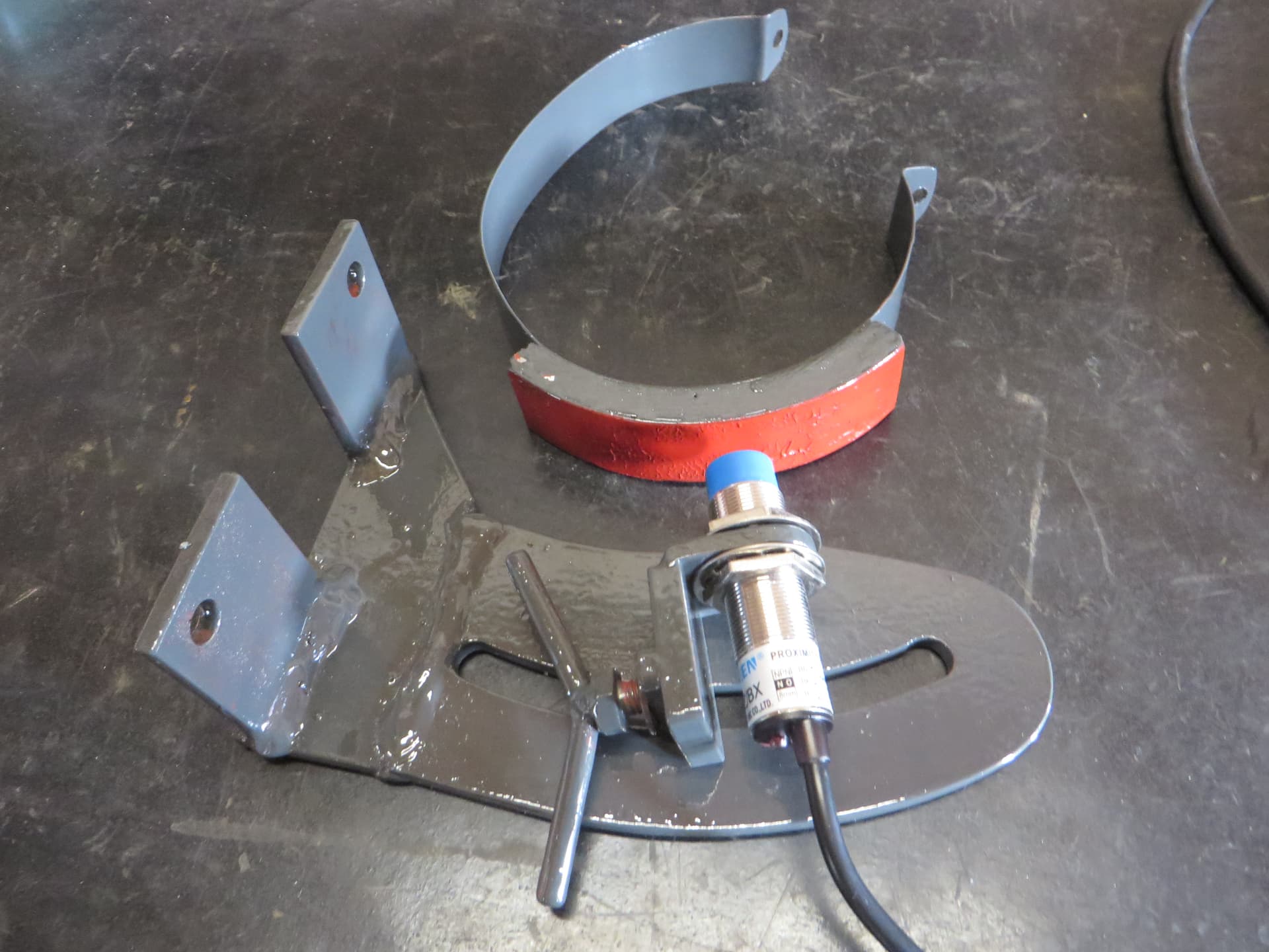
I had machine control implemented and working just fine, but was a bit worried that I might destroy the tractor electronics. So I removed it completely and bought a proximity switch used as a work switch to at least record the applied area and be able to use contour mode:


Update October 2022:
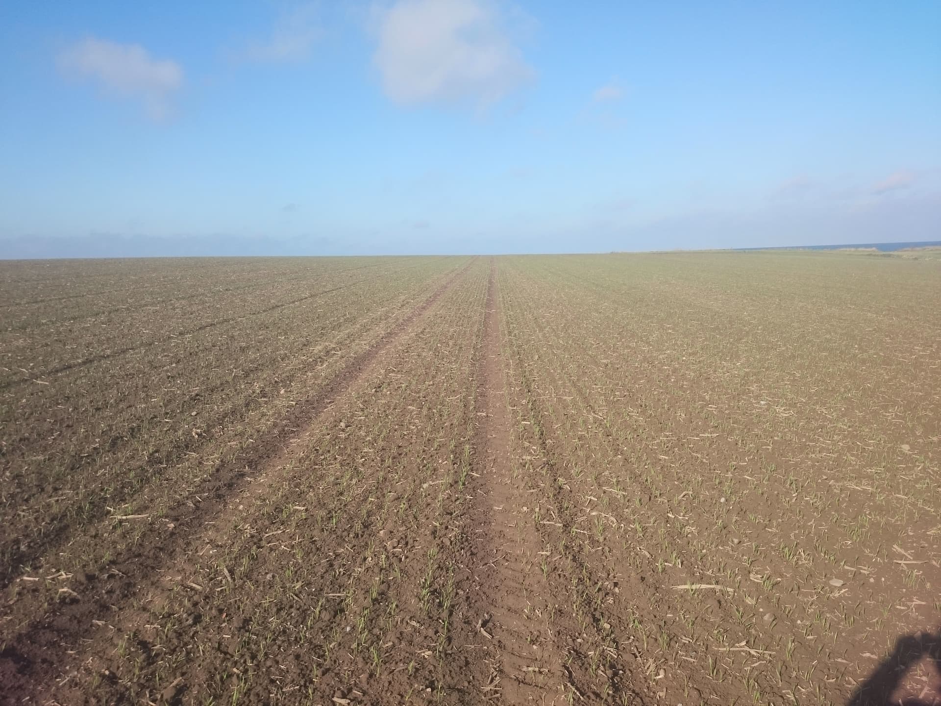
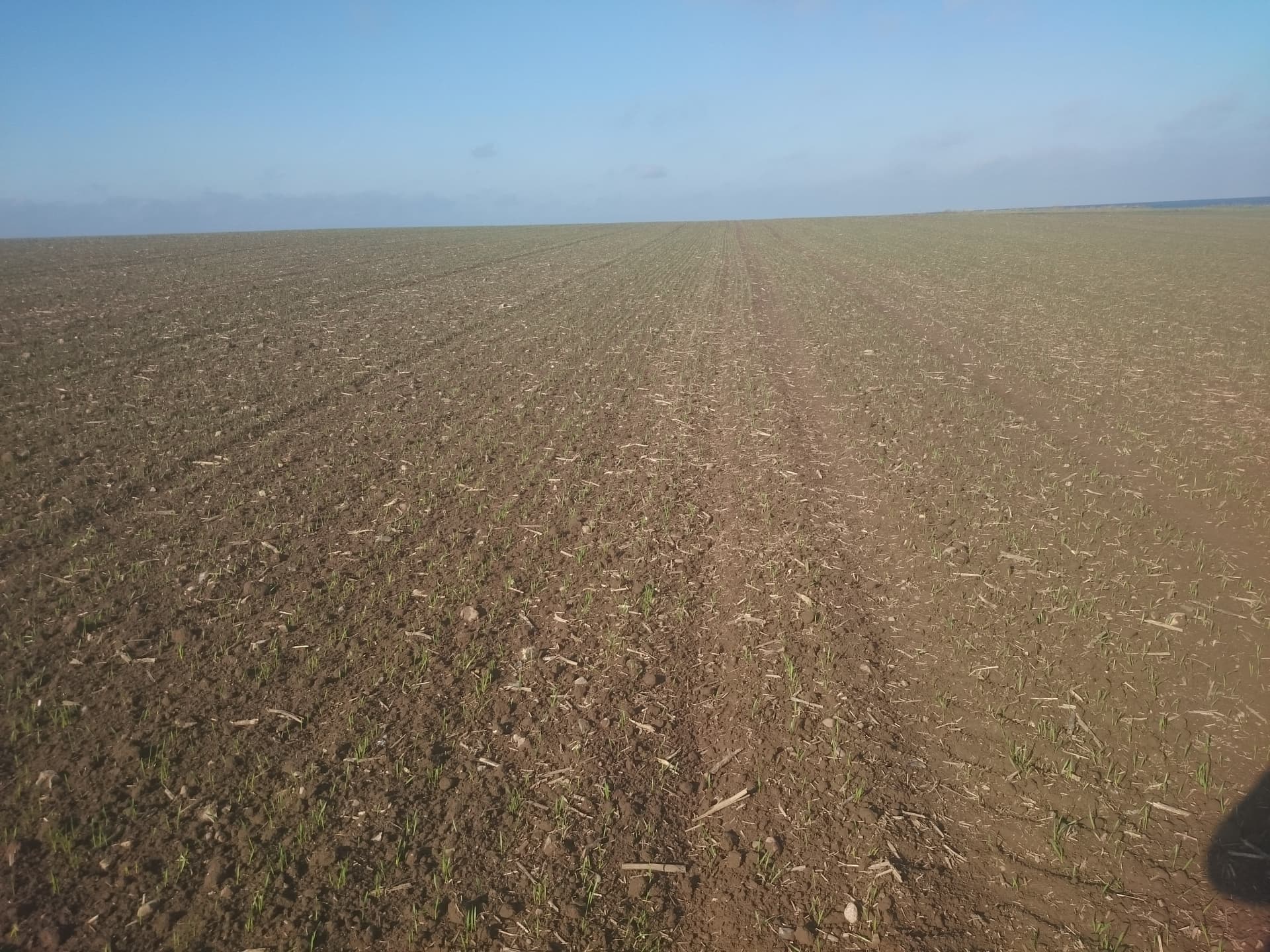
Seeding season 2022 is over. The work switch works perfect. This summer I only made a few changes: PANDA got set up and the antenna position was changed. After harvest I set up PANDA, hoping for better accuracy of the GPS position and heading. Had my antenna still on the roof of the (suspended) cabin. Maybe I expected too much from PANDA, but I was a bit disappointed by the results. Oilseed rape got seeded like that and wasnt looking very straight. Before going on to seed barley and wheat, kind of a last try, I moved the antenna to the front on the engine hood, approximately above the front axle. That was a game changer! The lines are now very straight, not perfect but Im absolutely fine with the result:

only thing to notice is a little offset I’m struggling with, I probably need some kind of physical marking behind my seeder, but thats not AOG’s fault. In summary after two seasons with AOG: with single and suspended cabin the antenna needs to be on the engine hood and it can steer very good. Not sure about PANDA. As said before, single point grounding makes USB super stable. Maybe an external LTE receiver would make sense, as in rural germany I have literally always problems with my internet connection…
